TDA9535L STMicroelectronics, TDA9535L Datasheet
TDA9535L
Specifications of TDA9535L
Available stocks


Related parts for TDA9535L


TDA9535L Summary of contents
Page 1
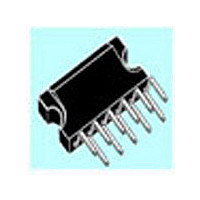
... Supply Voltage: 110V Perfectly matched with the TDA9210 Preamplifier Full Pin Compatibility with the TDA9535/36 DESCRIPTION The TDA9535L is a triple-channel video amplifier designed in BCD technology (Bipolar/CMOS/ DMOS) able to drive the 3 cathodes of a CRT monitor. Perfectly matched with the ST Preamplifier TDA9210, it provides a high performance, and very cost effective DC coupling system ...
Page 2
... TDA9535L 1 BLOCK DIAGRAM OF THE TDA9535L OUT1 GND1 REF 3 IN1 2 PIN CONNECTIONS Pin Name 1 OUT1 2 GND1 3 IN1 OUT2 6 GND2 7 IN2 IN3 10 GND3 11 OUT3 2/16 2 GND2 OUT2 REF 7 IN2 Function Output-Channel 1 Power Ground-Channel 1 Video Input-Channel 1 Amplifier High Supply Voltage Output-Channel 2 Power Ground-Channel 2/ Ground Substract ...
Page 3
... OG V Maximum Input Voltage IN Max V Minimum Input Voltage IN Min T Junction Temperature J T Storage Temperature STG 4 THERMAL DATA Symbol R Junction-Case Thermal Resistance (Max.) th (j-c) R Junction-Ambient Thermal Resistance (Typ.) th (j-a) Parameter Parameter TDA9535L Value Unit 120 300 0.5 V 150 °C -20 + 150 °C Value ...
Page 4
... VG Video Gain LE Linearity Error V Internal Voltage Reference REF Note 1: The TDA9535L goes into stand-by mode when Vcc is switched off (<1.5V). In stand-by mode, Vout is set to low level. Note 2: Matching measured between each channel. Note 3: Pulsed current width < 4/16 2 Test Conditions = 110V, Tamb = 25 °C, unless otherwise specified) ...
Page 5
... Test Conditions 1) (Note 50V, f=1MHz DC V =50V, V=20V DC V =50V, V=40V DC V =50V, V=40V DC V =50V, V=40V DC V =50V, V=20V MHz V =50V, V=20V 20MHz 12V 110V REF TDA9535L Min. Typ Max 8 OUT R = 200 =8pF L 2 GND Unit % % % MHz ns ns ...
Page 6
... TDA9535L 6 THEORY OF OPERATION 6.1 - General The TDA9535L is a three-channel video amplifier supplied by a low supply voltage: V and a high supply voltage The high values of V supplying the amplifier out- DD put stage control directly the CRT cathodes (DC coupling mode coupling mode, the application schematic is very simple and only a few external components are needed to drive the cathodes ...
Page 7
... Amplifier gain and cut-off adjustment A very simplified schematic of each TDA9535L channel is shown in Figure 3. The feedback net of each channel is integrated with a built-in voltage gain of 19.8 (40k/2k). Figure 3. Simplified schematic of one channel IN 7 ARCING PROTECTION As the amplifier outputs are connected to the CRT cathodes, special attention must be given to pro- tect them against possible arcing inside the CRT ...
Page 8
... Section 8.3). Figure 5. Video response optimization for one channel C11 4.7 F R20 TDA9207 TDA9209 IN 15/50 TDA9535L/ connected as close as possible to the device * 8.1 - Supply decoupling The decoupling of V and V CC quality HF capacitors (respectively C10 and C12) close to the device is necessary to improve the dy- namic performance of the video signal ...
Page 9
... L We have STAT Therefore 4.41W. TOT Note 4: = 110V 12V 40mA 40MHz 2.13W 3.04W DYN This worst thermal case must only be considered for TJmax calculation. Nevertheless, during the average life of the circuit, the conditions are closer to the white picture conditions. TDA9535L 9/16 ...
Page 10
... TDA9535L 10 TYPICAL PERFORMANCE CHARACTERISTICS V =110V, V =12V, C =8pF Figure 6. TDA9535L pulse response Figure 8. Power dissipation versus frequency Square Wave Frequency (MHz) (72% Active Tim e) Figure 10. Speed versus offset Off set Voltage (Vdc) 10/16 =300 , V=40V , unless otherwise specified - see P PP Figure 7. V Figure 9. Speed versus temperature ...
Page 11
... Figure 12. TDA9210 - TDA9535L/9536 Demonstration Board: Silk Screen and Trace Figure 13. Amplifier and Preamplifier Outputs. Trace Routing (detail) TDA9535L OUT1 OUT2 OUT3 13(b) 13(a) IN1 IN2 IN3 11/16 ...
Page 12
... TDA9535L Figure 14. TDA9535L/9536 - TDA9210 Demonstration Board Schematic 12/16 ...
Page 13
... TDA9535L Inches Min. Typ. Max. 0.116 0.118 0.120 0.037 0.039 0.041 0.006 0.051 0.059 0.066 0.019 0.020 ...
Page 14
... TDA9535L Table 1 Dimensions Min Note 5: “H3 and L2” do not include mold flash or protrusions 14/16 Millimeters Typ. Max. 3.30 3.40 0.30 0.50 0.70 0.75 10deg. 5deg. 75deg. Inches Min. Typ. Max. 0.126 0.130 0.134 0.012 0.019 0.025 0.027 0.029 10deg. 5deg. ...
Page 15
... TDA9535L 15/16 ...
Page 16
... No license is granted by implication or otherwise under any patent or patent rights of STMicroelectronics. Specifications mentioned in this publication are subject to change without notice. This publication supersedes and replaces all information previously supplied. STMicroelectronics products are not authorized for use as critical components in life support devices or systems without the express written approval of STMicroelectronics ...