HSDL-3602-007 Lite-On Electronics, HSDL-3602-007 Datasheet - Page 17
HSDL-3602-007
Manufacturer Part Number
HSDL-3602-007
Description
Infrared Transceivers IR Transceiver 4.0Mb/s
Manufacturer
Lite-On Electronics
Type
TX/RXr
Series
-r
Datasheet
1.HSDL-3602-007.pdf
(27 pages)
Specifications of HSDL-3602-007
Pulse Width
1.6/4us
Led Supply Voltage
-0.5 to 7V
Dimensions
12.2x4.9x4
Peak Wavelength
875/880nm
Angle Of Half Sensitivity
60/30°
Communication Distance
150
Fall Time
40/25ns
Rise Time
40/25ns
Operating Supply Voltage (typ)
3.3V
Operating Supply Voltage (min)
2.7V
Operating Supply Voltage (max)
3.6V
Mounting
Surface Mount
Pin Count
10
Operating Temp Range
-20C to 70C
Operating Temperature Classification
Commercial
Data Rate
3.90625Mbps
Wavelength
875 nm, 880 nm
Continual Data Transmission
4 Mbit/s
Transmission Distance
1.5 m
Radiant Intensity
250 mW/sr
Half Intensity Angle Degrees
30 deg to 60 deg
Maximum Rise Time
40 ns, 25 ns
Maximum Fall Time
40 ns, 25 ns
Maximum Forward Current
165 mA
Operating Voltage
2.7 V to 3.6 V
Maximum Operating Temperature
+ 70 C
Minimum Operating Temperature
- 20 C
Idle Current, Typ @ 25° C
2.5mA
Link Range, Low Power
1m
Operating Temperature
-20°C ~ 70°C
Orientation
Side View
Shutdown
Yes
Size
12.2mm x 4.9mm x 4mm
Standards
IrPHY 1.4
Supply Voltage
2.7 V ~ 3.6 V
Lead Free Status / RoHS Status
Compliant
Lead Free Status / RoHS Status
Lead free / RoHS Compliant, Compliant
Available stocks
Company
Part Number
Manufacturer
Quantity
Price
Company:

Part Number:
HSDL-3602-007
Manufacturer:
LITEON
Quantity:
163
Part Number:
HSDL-3602-007
Manufacturer:
AVAGO/安华高
Quantity:
20 000


17
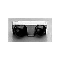
3.1. Tolerance for X-axis Alignment of Castellation
Misalignment of castellation to the land pad should not exceed 0.2 mm or approximately half the width of the cas-
tellation during placement of the unit. The castellations will completely self-align to the pads during solder reflow as
seen in the pictures below.
Picture 1. Castellation misaligned to land pads in X-axis before
reflow.
3.2. Tolerance for Rotational (Theta) Misalignment
Units when mounted should not be rotated more than ± 2 degrees with reference to center X-Y as specified in Fig-
ure 2. Pictures 3 and 4 show units before and after reflow. Units with a Theta misalignment of more than 2 degrees
do not completely self-align after reflow. Units with ± 2 degree rotational or Theta misalignment self-aligned com-
pletely after solder reflow.
Picture 3. Unit is rotated before reflow.
Picture 2. Castellation self-align to land pads after reflow.
Picture 4. Unit self-aligns after reflow.
Related parts for HSDL-3602-007
Image
Part Number
Description
Manufacturer
Datasheet
Request
R

Part Number:
Description:
EMITTER IR 5MM 875NM
Manufacturer:
Lite-On Electronics
Datasheet:

Part Number:
Description:
ENCODER/DECODER 3/16 8-SOIC
Manufacturer:
Lite-On Electronics
Datasheet:

Part Number:
Description:
PHOTOSENSOR MINI 3V 550NM 6-PLCC
Manufacturer:
Avago Technologies US Inc.

Part Number:
Description:
Infrared Transceivers IR Transceiver 115.2Kb/s
Manufacturer:
Lite-On Electronics
Datasheet:

Part Number:
Description:
Infrared Transceivers FIR + RC
Manufacturer:
Avago Technologies US Inc.
Datasheet:

Part Number:
Description:
Manufacturer:
Avago Technologies
Datasheet:

Part Number:
Description:
Manufacturer:
Agilent Technologies, Inc.
Datasheet:
Part Number:
Description:
EMITTER IR FLAT 875NM SHORT LDS
Manufacturer:
Lite-On Electronics
Datasheet:
Part Number:
Description:
EMITTER IR FLAT 875NM LONG LDS
Manufacturer:
Lite-On Electronics
Datasheet:
Part Number:
Description:
EMITTER IR 5MM HI POWER 870NM
Manufacturer:
Lite-On Electronics
Part Number:
Description:
Standard LED - SMD Polyled Emmiter Long Leads
Manufacturer:
Lite-On Electronics
Datasheet:

Part Number:
Description:
IC ENCODER/DECODER IRDA 16-SOIC
Manufacturer:
Lite-On Electronics
Datasheet:

Part Number:
Description:
IC ENCODER/DECODER IRDA 16-QFN
Manufacturer:
Lite-On Electronics
Datasheet:
Part Number:
Description:
ENCODER/DECODER 3/16 8-SOIC
Manufacturer:
Lite-On Electronics
Datasheet:
Part Number:
Description:
ENCODER/DECODER 3/16 CLK 16-SOIC
Manufacturer:
Lite-On Electronics
Datasheet: