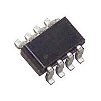
LTC2905CTS8#PBF Linear Technology, LTC2905CTS8#PBF Datasheet - Page 9

LTC2905CTS8#PBF
Manufacturer Part Number
LTC2905CTS8#PBF
Description
Manufacturer
Linear Technology
Datasheet
1.LTC2905CTS8PBF.pdf
(16 pages)
Specifications of LTC2905CTS8#PBF
Voltage Supervisor Type
Voltage Monitor
Number Of Voltage Supervisors
2
Operating Supply Voltage (min)
1V
Package Type
TSOT-23
Operating Temperature Classification
Commercial
Operating Temp Range
0C to 70C
Pin Count
8
Mounting
Surface Mount
Lead Free Status / RoHS Status
Compliant
Available stocks
Company
Part Number
Manufacturer
Quantity
Price
APPLICATIONS INFORMATION
Supply Monitoring
The LTC2904/LTC2905 are low power, high accuracy dual
supply monitors with a common reset output and selectable
thresholds. Reset delay is set to a nominal of 200ms for
the LTC2904 and is adjustable using an external capacitor
for the LTC2905.
The two 3-state input pins (S1 and S2) select one of nine
possible threshold voltage combinations. Another three-
state input pin sets the supply tolerance (5%, 7.5% or
10%). Both input voltages (V1 and V2) must be above
predetermined thresholds for the reset not to be invoked.
The LTC2904/LTC2905 assert the reset outputs during
power-up, power-down and brownout conditions on either
of the voltage inputs.
Power-Up
The greater of V1, V2 is the internal supply voltage (V
V
soon as V1 or V2 reaches 1V during power-up, the RST
output asserts low.
V
LTC2904. Therefore, RST weakly pulls high when V1 or
V2 reaches at least 1V.
Threshold programming is complete when V1 reaches
at least 2.17V. After programming, if either V1 or V2 falls
below its programmed threshold, RST asserts low (RST
weakly pulls high) as long as V
Once V1 and V2 rise above their thresholds, an internal
timer is started. After the programmed delay time, RST
weakly pulls high (RST asserts low).
Power-Down
On power-down, once either V1 or V2 inputs drops below
its threshold, RST asserts logic low and RST weakly pulls
high. V
RST.
Programming Pins
The three 3-state input pins: S1, S2 and TOL should be
connected to GND, V1 or left unconnected during normal
operation. Note that when left unconnected, the maximum
CC
CC
powers the drive circuits for the RST pin. Therefore as
also powers the drive circuits for the RST pin in the
CC
of at least 1V guarantees a logic low of 0.4V at
CC
is at least 1V.
CC
).
leakage current allowable from the pin to either GND or
V1 is 10μA.
In margining applications, all the 3-state input pins can be
driven using a tri-state buffer. Note however the low and
high output of the tri-state buffer has to satisfy the V
V
Table. Moreover, when the tri-state buffer is in the high
impedance state, the maximum leakage current allowed
from the pin to either GND or V1 is 10μA.
Monitor Programming
Connecting S1 and S2 to GND, V1 or leaving them open
selects the LTC2904/LTC2905 input voltage combina-
tions. Table 1 shows the nine possible combinations of
nominal input voltages and their corresponding S1, S2
connections.
Table 1. Voltage Threshold Programming
Note: Open = open circuit or driven by a three state buffer in high
impedance state with leakage current less than 10μA.
Tolerance Programming
The three-state input pin, TOL programs the common
supply tolerance for both V1 and V2 input voltages (5%,
7.5% or 10%). The larger the tolerance the lower the trip
threshold. Table 2 shows the tolerances selection corre-
sponding to a particular connection at the TOL pin.
IH
of the 3-state pin listed in the Electrical Characteristics
5.0
3.3
3.3
3.3
3.3
2.5
2.5
2.5
2.5
V1
Table 2. Tolerance Programming
Tolerance
7.5%
10%
5%
3.3
2.5
1.8
1.5
1.2
1.8
1.5
1.2
1.0
LTC2904/LTC2905
V2
Open
Open
Open
GND
GND
GND
Open
GND
TOL
S1
V1
V1
V1
V1
Open
Open
Open
GND
GND
GND
S2
V1
V1
V1
IL
29045fc
9
and


