ADM1070ARTZ Analog Devices Inc, ADM1070ARTZ Datasheet
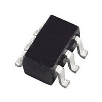
ADM1070ARTZ

Manufacturer Part Number
ADM1070ARTZ
Description
Manufacturer
Analog Devices Inc
Datasheet

Specifications of ADM1070ARTZ

Linear Misc Type
Negative Voltage
Family Name
ADM1070
Package Type
SOT-23
Operating Supply Voltage (min)
-18V
Operating Supply Voltage (max)
-80V
Operating Temperature (min)
-40C
Operating Temperature (max)
85C
Operating Temperature Classification
Industrial
Product Depth (mm)
1.6mm
Product Height (mm)
1.15mm
Product Length (mm)
2.9mm
Mounting
Surface Mount
Pin Count
6
Lead Free Status / RoHS Status
Compliant

Available stocks

Company
Part Number
Manufacturer
Quantity
Price
Part Number:
ADM1070ARTZ-REEL7
Manufacturer:
ADI/亚德诺
Quantity:
20 000
Company:
Part Number:
ADM1070ARTZ-REEL7
Quantity:
3 500
Part Number:
ADM1070ARTZREEL7
Manufacturer:
NSC
Quantity:
3 449
a
GENERAL DESCRIPTION
The ADM1070 is a negative voltage hot swap controller that
allows a board to be safely inserted and removed from a live
–48 V backplane. The part achieves this by providing robust
current limiting, protection against transient and nontransient
short circuits and overvoltage and undervoltage conditions. The
ADM1070 typically operates from a negative voltage of up to
–80 V and can tolerate transient voltages of up to –200 V.
In-rush current is limited to a programmable value by control-
ling the gate drive of an external N-channel FET. The current
limit can be controlled by the choice of the sense resistor,
R
on-chip timer that uses pulsewidth modulation to allow the
maximum current to flow for only 3% of the time. An autorestart
occurs after a current limit timeout. After seven successive
autorestarts, the fault will be latched and the part goes into
shutdown with the result that the external FET is disabled until
the power is reset.
REV. 0
Information furnished by Analog Devices is believed to be accurate and
reliable. However, no responsibility is assumed by Analog Devices for its
use, nor for any infringements of patents or other rights of third parties that
may result from its use. No license is granted by implication or otherwise
under any patent or patent rights of Analog Devices.
SENSE
FEATURES
Allows Safe Board Insertion and Removal from a Live
Typically Operates from –36 V to –80 V
Tolerates Transients up to –200 V (Limited by External
Accurate Programmable Linear Current Limit for
Programmable Timeout in Current Limit
Limited Consecutive Retry:
Default Timing Provided with no TIMER Capacitor
Single Pin Undervoltage/Overvoltage Detection
Programmable Operating Voltage Window
Programmable Undervoltage/Overvoltage Time Filter
Small 6-Lead SOT-23 Package
APPLICATIONS
Central Office Switching
–48 V Distributed Power Systems
Negative Power Supply Control
Hot Board Insertion
Electronic Circuit Breaker
High Availability Servers
Programmable Current Limiting Circuit
–48 V Power Supply Modules
–48 V Backplane
Components)
In-Rush Control and Short Circuit Protection
Auto-Restart after Current Limit Timeout
Shutdown after Seven Consecutive Auto Restarts
Provides Immunity from Step Induced Current Spikes
. Added control of the in-rush current is provided by an
The ADM1070 also features single-pin undervoltage and over-
voltage detection. The FET is turned off if a nontransient
voltage less than the undervoltage threshold, typically –36 V, or
greater than the overvoltage threshold, typically –77 V, is detected
on the UV/OV Pin. The operating voltage window of the
ADM1070 is programmable and is determined by the ratio R1/R2.
Time filtering on the undervoltage and overvoltage detection
and current limiting is programmable via the TIMER Pin. An
external capacitor connected between the TIMER Pin and V
determines the undervoltage/overvoltage time filter and the
timeout in current limit. If the pin is tied to V
values and the current limit timeout revert to default figures.
The ADM1070 is fabricated using BiCMOS technology for mini-
mal power consumption. The part is available in a small
6-Lead SOT-23 package.
One Technology Way, P.O. Box 9106, Norwood, MA 02062-9106, U.S.A.
Tel: 781/329-4700
Fax: 781/326-8703
–48V
V
V
R1
R2
0V
EE
DD
TIMER
UV/OV
(
)*
–48 V Hot Swap Controller
FUNCTIONAL BLOCK DIAGRAM
VOLTAGE DETECTION
OSCILLATOR
FAULT TIMER AND
*OPTIONAL TIMER CAPACITOR
OVER-UNDER
CONTROL
R
CIRCUIT
DROP
12V
ADM1070
16k
V
IN
GENERATOR
REFERENCE
V
CC
100mV
AND
© Analog Devices, Inc., 2002
ADM1070
EN
V
V
REF
V
CC
IN
45 A
EE
, the time filter
www.analog.com
GATE
SENSE
V
EE
C
LOAD
R
Q1
EE
SENSE
V
OUT

Related parts for ADM1070ARTZ

ADM1070ARTZ Summary of contents

Page 1

FEATURES Allows Safe Board Insertion and Removal from a Live –48 V Backplane Typically Operates from – –80 V Tolerates Transients up to –200 V (Limited by External Components) Accurate Programmable Linear Current Limit for In-Rush Control ...

Page 2

ADM1070–SPECIFICATIONS Parameter BOARD SUPPLY (not connected directly to device) Maximum Voltage Range Typical Operating Voltage Range VIN PIN––SHUNT REGULATOR Operating Supply Voltage Range Quiescent Supply Current Maximum Shunt Supply Voltage Undervoltage Lockout, V LKO ...

Page 3

Parameter SENSE PIN––CURRENT SENSE (continued) Continuous Short Circuit Time before Latched Shutdown, t SHORT Operating Sense Voltage Range, V SOP Input Current, I SENSE TIMER PIN––TIMING CONTROL Internal Oscillator Default Frequency, f (Not Seen at Pin) TIMERINT External/Internal Selection Threshold, ...

Page 4

ADM1070 Pin No. Mnemonic Function 1 SENSE Connection to External FET Source Voltage. A sense resistor is connected in the supply path between the SENSE Pin and V faults. This voltage is fed as an input to the linear current ...

Page 5

TEMPERATURE – C TPC 1. I vs. Temperature IN 1000 100 10 + + ...

Page 6

ADM1070 120 115 110 105 100 –50 –35 –20 – TEMPERATURE – C TPC 7. Analog Current Limit Voltage, V Temperature 150 145 140 135 130 125 120 115 110 105 100 –50 –35 ...

Page 7

V – V GATE TPC 13. I vs. V GATE 4.0 3.5 3.0 2.5 2.0 1.5 1.0 0.5 0 –50 –35 ...

Page 8

ADM1070 4.0 3.5 3.0 2.5 2.0 1.5 1.0 0.5 0 –50 –35 –20 – TEMPERATURE – C TPC 19. POR Delay vs. Temperature 4.0 3.5 3.0 2.5 2.0 1.5 - 1.0 0.5 0 –50 –35 –20 –5 10 ...

Page 9

FUNCTIONAL DESCRIPTION HOT CIRCUIT INSERTION Inserting circuit boards into a live –48 V backplane can cause large transient currents to be drawn as the board capacitance charges up. These transient currents can cause glitches on the system power supply and ...

Page 10

ADM1070 voltage between the SENSE and V 100 mV (the analog current limit voltage) during t then the ADM1070 takes action to reduce this current to a safer level. The internal analog current limit loop dynami- cally ...

Page 11

UNDERVOLTAGE/OVERVOLTAGE DETECTION The ADM1070 incorporates single-pin overvoltage and undervoltage detection with a programmable operating voltage window. When the voltage on the UV/OV pin rises above the OV rising threshold or falls below the UV falling threshold, a fault signal is ...

Page 12

ADM1070 FUNCTIONALITY AND TIMING Live Insertion The timing waveforms associated with the live insertion of a plug-in board using the ADM1070 are shown in the following figures. When the board connects the GND-V climbs this voltage ...

Page 13

CURRENT FAULT PLOTS Some timing waveforms associated with current over faults are shown in the following figures. Figure 9 shows how a current glitch (of approximately 500 µs) is dealt with when the output is shorted after power-up. The gate ...

Page 14

ADM1070 Figure 13 shows the behavior of ADM1070 when a temporary current fault occurs followed by a permanent current fault. When the first overcurrent fault occurs, the first 100 mV spike on the sense line can be seen. During the ...

Page 15

MAX REV. 0 OUTLINE DIMENSIONS 6-Lead Plastic Surface-Mount Package [SOT-23] (RT-6) Dimensions shown in millimeters 2.90 BSC 2.80 BSC 1.60 BSC PIN 1 0.95 BSC 1.90 1.30 BSC 1.15 0.90 1.45 MAX 0.22 ...

Page 16

–16– ...

Related keywords