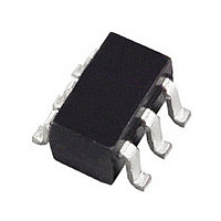
ADM1070ARTZ Analog Devices Inc, ADM1070ARTZ Datasheet - Page 10

ADM1070ARTZ
Manufacturer Part Number
ADM1070ARTZ
Description
Manufacturer
Analog Devices Inc
Datasheet
1.ADM1070ARTZ.pdf
(16 pages)
Specifications of ADM1070ARTZ
Linear Misc Type
Negative Voltage
Family Name
ADM1070
Package Type
SOT-23
Operating Supply Voltage (min)
-18V
Operating Supply Voltage (max)
-80V
Operating Temperature (min)
-40C
Operating Temperature (max)
85C
Operating Temperature Classification
Industrial
Product Depth (mm)
1.6mm
Product Height (mm)
1.15mm
Product Length (mm)
2.9mm
Mounting
Surface Mount
Pin Count
6
Lead Free Status / RoHS Status
Compliant
Available stocks
Company
Part Number
Manufacturer
Quantity
Price
Part Number:
ADM1070ARTZ-REEL7
Manufacturer:
ADI/亚德诺
Quantity:
20 000
Company:
Part Number:
ADM1070ARTZREEL7
Manufacturer:
NSC
Quantity:
3 449
ADM1070
2. If a voltage between the SENSE and V
3. If a serious short circuit occurs on the load side, the –48 V
SENSE RESISTOR
The ADM1070’s current limiting function can operate at differ-
ent current levels. The sense resistor is inserted between the V
and sense pins, and a current fault occurs whenever the voltage
across the sense resistor is greater than 100 mV for longer than
the on time, t
tion of the sense resistor, R
maximum allowable load current (I
mum and maximum in-rush currents (I
are related to the value of R
R
(m )
5
10
15
18
22
33
47
51
68
75
90
SENSE
100 mV (the analog current limit voltage) during t
then the ADM1070 takes action to reduce this current to a
safer level. The internal analog current limit loop dynami-
cally adjusts the gate drive, keeping the load current at the
100 mV/R
source, limiting the load current to the level set by the value
of the sense resistor.
The sense voltage is also above the circuit breaker limit voltage,
so the limited consecutive retry function is still operational. If
the current fault is not cleared (sense resistor voltage brought
below 79 mV) after seven consecutive faults, then the device
is latched off.
supply can cause massive currents to flow very quickly.
Because of this, the gate voltage must be reduced quickly to
prevent a catastrophic failure. If the ADM1070 detects a
voltage greater than the fast current limit voltage (126 mV)
across the sense resistor, it is apparent that a serious short
circuit is present and the load current must be reduced as
quickly as possible. The fast current limit loop takes over and
pulls gate low much faster than in the previous case.
Table I. I
for Different Values of R
LIMITON
SENSE
I
(A)
12.0
6.0
4.0
3.3
2.7
1.8
1.3
1.2
0.9
0.8
0.7
LOAD(MAX)
LOAD(MAX)
level. The FET now acts as a current
. The current limit is determined by selec-
SENSE
, I
SENSE
LIMIT(MIN)
.
I
(A)
18.0
9.0
6.0
5.0
4.1
2.7
1.9
1.7
1.3
1.2
1.0
LIMIT(MIN)
SENSE
. Table I shows how the
LOAD(MAX)
LIMIT(MIN)
, and I
EE
) and the mini-
Pins increases to
LIMIT(MAX)
) and I
I
(A)
22.0
11.0
7.3
6.1
5.0
3.3
2.3
2.2
1.6
1.5
1.2
LIMIT(MAX)
LIMITON
LIMIT(MAX)
,
EE
)
–10–
INTERNAL UNDERVOLTAGE LOCKOUT
The V
voltage at V
this voltage drops below 8.5 V, the device is disabled and gate is
pulled low. Note that this is unrelated to the undervoltage
and overvoltage functions performed at the UV/OV Pin.
TIMER
The TIMER Pin on the ADM1070 gives the user control over
the timing functions on the part. By connecting an external
capacitor between the TIMER Pin and V
UV/OV glitch filter time, t
t
out, t
shutdown, t
relative to each other and cannot be altered individually (without
changing the other times). The default values for these times are
selected by tying the TIMER Pin directly to V
C
(pF)
220
330
470
Tied to V
680
1000
2200
SHUNT REGULATOR
A shunt regulator shunts the ADM1070 V
derived from the –48 V supply through the combination of an
internal Zener diode and an external shunt resistor, R
Table II shows the operational voltage range and power dissipa-
tion for different values of R
value for R
R
10 kΩ (0.25 W) 26
12 kΩ
14 kΩ
16 kΩ
18 kΩ
20 kΩ
22 kΩ
10 kΩ (0.5 W) 26
12 kΩ
14 kΩ
16 kΩ
18 kΩ
20 kΩ
22 kΩ
POR
DROP
TIMER
Table II. Minimum and Maximum Allowable Operating
Voltages for Different Values of R
, the maximum current on time, t
Table III. Timer Capacitor Values and Timing Values
OFF
IN
, and the continuous short circuit time before latched
Pin is monitored for undervoltage lockout. When the
EE
DROP
IN
SHORT
is above 8.5 V (V
2.54
5.64
t
(ms)
0.58
0.85
1.21
1.55
1.74
.
FLT
Min Allowable
V
(V)
28.6
31.2
33.8
36.4
39
41.6
28.6
31.2
33.8
36.4
39
41.6
(see Table III). Note that all times are scaled
DD
Voltage
t
(ms)
0.58
0.85
1.21
1.55
1.74
2.54
5.64
POR
FLT
DROP
, the power-on reset delay time,
LKO
. Note that 16 kΩ is the default
t
(ms)
4.8
7.1
9.9
12.8
14.2
20.8
46.2
LIMITON
), the device is enabled. If
Max Allowable
V
(V)
61
65.8
70.2
74.2
78.1
81.7
85.2
81.7
88.5
94.7
100.4
105.9
111
115.9
DROP
ON
DD
, the current limit time
EE
Voltage
, the user can set the
IN
t
(ms)
150
230
320
410
450
660
1465
PWMOFF
EE
Pin. Power is
.
DROP
P
@ 48 V
(W)
0.13
0.11
0.09
0.08
0.07
0.065
0.06
0.13
0.11
0.09
0.08
0.07
0.065
0.06
REV. 0
t
(ms)
1000
1400
2000
2600
2800
4100
9113
SHORT
DROP
.


