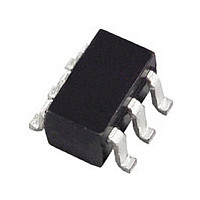
ADM1070ARTZ Analog Devices Inc, ADM1070ARTZ Datasheet - Page 13

ADM1070ARTZ
Manufacturer Part Number
ADM1070ARTZ
Description
Manufacturer
Analog Devices Inc
Datasheet
1.ADM1070ARTZ.pdf
(16 pages)
Specifications of ADM1070ARTZ
Linear Misc Type
Negative Voltage
Family Name
ADM1070
Package Type
SOT-23
Operating Supply Voltage (min)
-18V
Operating Supply Voltage (max)
-80V
Operating Temperature (min)
-40C
Operating Temperature (max)
85C
Operating Temperature Classification
Industrial
Product Depth (mm)
1.6mm
Product Height (mm)
1.15mm
Product Length (mm)
2.9mm
Mounting
Surface Mount
Pin Count
6
Lead Free Status / RoHS Status
Compliant
Available stocks
Company
Part Number
Manufacturer
Quantity
Price
Part Number:
ADM1070ARTZ-REEL7
Manufacturer:
ADI/亚德诺
Quantity:
20 000
Company:
Part Number:
ADM1070ARTZREEL7
Manufacturer:
NSC
Quantity:
3 449
CURRENT FAULT PLOTS
Some timing waveforms associated with current over faults are
shown in the following figures. Figure 9 shows how a current
glitch (of approximately 500 µs) is dealt with when the output is
shorted after power-up. The gate voltage is at a constant 12.3 V
before the glitch occurs. When the short circuit occurs, the
sense voltage rises sharply as the load current ramps up quickly.
When the sense voltage reaches 100 mV (V
reduces the gate voltage to stop the load current from increasing
any further. When V
voltage is increased again.
The plots shown illustrate the operation of the ADM1070’s
unique limited consecutive retry function. Figure 10 highlights
what happens when a current fault occurs for more than 14 ms
(default t
fault is registered. In this case, gate is previously low and the
part is being powered up into a current fault situation (shorted
load). When power is applied, gate is allowed to ramp until
sense reaches 100 mV. gate is then held constant to keep sense
at this level. After t
reduced to zero.
REV. 0
SENSE
SENSE
Figure 10. Timing Waveforms Associated with a
Current Fault
Figure 9. Timing Waveforms Associated with a
Current Glitch
GATE
GATE
V
OUT
LIMITON
CH1
CH3
CH1
10.00V
20.00V
when TIMER Pin tied to V
5.00V
ON
SENSE
, the PWM cycle begins and gate is
CH2
CH2
drops back below V
14ms
100mV M 500 s
100mV M
T
T
T
5.00 s
ACL
EE
), the ADM1070
ACL
) and a current
CH2
CH1
, the gate
1.4V
34mV
–13–
Figure 11 shows a current fault on a wider timebase. The first
spike on the sense line represents the first current fault. The
sense voltage is allowed to ramp up to 100 mV before the gate
voltage is reduced to compensate. The gate and sense voltages
remain at these levels until the t
fault is then registered and the gate voltage, and therefore the
sense voltage, are then both held low for the time period t
Note that the PWM ratio (t
then restarts and the sense voltage is free to ramp up to 100 mV
again (it will if the fault is still present). This cycle repeats itself
a total of seven times. Figure 12 shows the seven consecutive
faults occurring on an even wider timebase. If the ADM1070
detects seven consecutive current faults, the part then latches off
(after a total time t
SENSE
SENSE
Figure 11. Illustration of the PWM Ratio (t
Figure 12. Illustration of the Limited Consecutive
Retry Function (Seven Retries and Latch Off)
GATE
GATE
CH1
CH3
CH1
CH3
t
ON
1.00V
5.00V
1.00V
5.00V
SHORT
).
CH2
CH2
t
OFF
ON
t
SHORT
/t
OFF
100mV M 100ms
ON
100mV M 100ms
) is equal to 3%. The cycle
time has expired. A current
ADM1070
ON
/t
OFF
OFF
)
.


