BZE6-7RNT Honeywell, BZE6-7RNT Datasheet - Page 7
BZE6-7RNT
Manufacturer Part Number
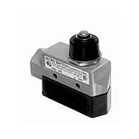
BZE6-7RNT
Description
Basic / Snap Action / Limit Switches Top Plunger Actuator 14 NPT conduit
Manufacturer
Honeywell
Type
Basicr
Specifications of BZE6-7RNT
Pole Throw Configuration
SPDT
Switch Function Configuration
N.O./N.C.
Current Rating (max)
15A
Terminal Type
Screw
Contact Form
SPDT - 1 NC / 1 NO
Contact Rating
15 Amps
Actuator
Plunger
Operating Force
7.78 N to 15.01 N
Termination Style
Screw
Ingress Protection
IP66 / NEMA 1, 3, 4
Actuator Type
Plunger
Brand/series
E6 Series
Current, Rating
0.5 A
Ip Rating
IP54
Material, Contact
Zinc Die-Cast (Housing)
Mounting Type
Side Mount
Number Of Poles
1
Number Of Positions
2
Standards
UL Recognized, CSA Certified, NEMA Approved
Temperature, Operating
-32 to +71 °C
Termination
Screw
Lead Free Status / RoHS Status
Compliant


Basic Switches
B Type Switches Performance Information
ELECTRICAL DATA CHART, cont.
1 For a 86 F (30 C) max. temperature rise at terminals, not opening or closing the load (at sea level).
2 Data established with a 75% power factor on AC loads.
TEST CONDITIONS
Switch contact life is affected by electrical conditions and other
factors, such as: temperature, humidity, airborne contamina-
tion, vibration, amount and rate of plunger travel, and cycling
MICRO SWITCH believes that with the following voltage and
current values and under the test conditions set forth below
switch life of 100,000 closures, 95% survival can be expected. It
is a starting point for user evaluation and provides guidelines
on the switches identified. Because of the numerous electrical
conditions listed, not every current and voltage level has ac-
tually been tested on every switch and certain figures have
For application help: call 1-800-537-6945.
Catalog
Listing
(contact
gap)
BZ-2R
.020 in.
0.50 mm
BZ-2R
.020 in.
0,50 mm
BZ-3R
.036 in.
0,91 mm
BZ-3R
.036 in.
0,91 mm
BZ-7R
.070 in.
1,78 mm
BZ-7R
.070 in.
1,78 mm
Temperature:
Humidity:
AC Cycle Rate:
DC Cycle Rate:
On-off Time:
Power Factor (AC): Approximately 75%.
Inductance (DC):
Circuit Loading:
Travel Plunger:
Actuation:
Overtravel Force:
Voltage
VDC
VDC
VDC
VAC
VAC
VAC
125
230
125
250
277
460
125
250
125
250
277
460
125
250
120
240
277
460
14
30
14
30
14
30
8
8
8
Amperes
Current
Carrying
Capacity
Max.
15
15
15
15
15
15
15
15
15
15
15
15
15
15
15
15
15
15
30
15
15
15
15
15
15
15
15
Room Ambient (70 F, 21 C).
Room Ambient (50%).
60 operations/minute.
20 operations/minute.
Equal and compatible with above cycling rates.
MIL-I-81023 Inductor.
One throw only on a SPDT switch during any test procedure. Both throws are evaluated separately.
Full switch travel is used.
Linear motion.
1 to 3 lbs. from spring-loaded actuators.
1
Resistive Ckt.
15
15
6
0.4
0.2
15
15
15
15
15
15
10
0.6
0.3
15
15
15
15
15
15
15
0.75
0.3
15
15
15
15
Inrush
N.C.
30
30
30
4
2
30
30
30
30
30
30
30
6
3
30
30
30
30
15
30
30
7.5
3
30
30
30
30
N.O.
Ckt.
15
15
15
4
2
15
15
15
15
15
15
15
6
3
15
15
15
15
5
15
15
7.5
3
15
15
15
15
Motor
N.C.
Ckt.
5
5
5
0.8
0.4
5
5
5
5
5
5
5
1.2
0.6
5
5
5
4
2.5
5
5
1.5
0.6
5
5
5
5
rate. Our Evaluation Laboratory tests are conducted using pro-
cedures and practices common to UL and Military Specifica-
tions. The following conditions generally apply.
been extrapolated. For specific switch selection, customers
should evaluate switches under actual application conditions
or by simulating all application conditions and requirements.
The information set forth cannot substitute for the customer’s
own product evaulation. It should never be published by a cus-
tomer as a rating on their product.
Honeywell Sensing and Control
N.O.
Ckt.
2.5
2.5
2.5
0.8
0.4
2.5
2.5
2.5
2.5
2.5
2.5
2.5
1.2
0.6
2.5
2.5
2.5
2.5
3
2.5
2.5
1.5
0.6
2.5
2.5
2.5
2.5
Lamp
N.C.
Ckt.
3
3
3
0.4
0.2
3
3
3
3
3
3
3
0.6
0.3
3
3
3
3
1.5
3
3
0.75
0.3
3
3
3
3
N.O.
Ckt.
1.5
1.5
1.5
0.4
0.2
1.5
1.5
1.5
1.5
1.5
1.5
1.5
0.6
0.3
1.5
1.5
1.5
1.5
15
1.5
1.5
0.75
0.3
1.5
1.5
1.5
1.5
Inductive
Sea
Level
15
10
5
0.05
0.03
15
15
15
15
15
15
10
0.1
0.05
15
15
15
15
15
15
10
0.4
0.2
15
15
15
15
97
2
50,000
Feet
15
8
2
0.03
0.02
15
15
15
15
15
15
5
0.05
0.03
15
15
15
15
—
15
7.5
0.2
0.1
15
15
15
15
Related parts for BZE6-7RNT
Image
Part Number
Description
Manufacturer
Datasheet
Request
R

Part Number:
Description:
Basic / Snap Action / Limit Switches Limit Switch E6 ENCLOSURES(BZE6)
Manufacturer:
Honeywell

Part Number:
Description:
Basic / Snap Action / Limit Switches E6 ENCLOSURES(BZE6)
Manufacturer:
Honeywell

Part Number:
Description:
Basic / Snap Action / Limit Switches Limit Switch E6 ENCLOSURES(BZE6)
Manufacturer:
Honeywell

Part Number:
Description:
Basic / Snap Action / Limit Switches Limit Switch E6 ENCLOSURES(BZE6)
Manufacturer:
Honeywell

Part Number:
Description:
Basic / Snap Action / Limit Switches Limit Switch E6 ENCLOSURES(BZE6)
Manufacturer:
Honeywell
Part Number:
Description:
Basic / Snap Action / Limit Switches E6 ENCLOSURES(BZE6)
Manufacturer:
Honeywell

Part Number:
Description:
Basic / Snap Action / Limit Switches Limit Switch E6 ENCLOSURES(BZE6)
Manufacturer:
Honeywell

Part Number:
Description:
Basic / Snap Action / Limit Switches Limit Switch E6 ENCLOSURES(BZE6)
Manufacturer:
Honeywell

Part Number:
Description:
Basic / Snap Action / Limit Switches Limit Switch E6 ENCLOSURES(BZE6)
Manufacturer:
Honeywell

Part Number:
Description:
SWITCH TOP PLUNGER SPDT 15A
Manufacturer:
Honeywell Sensing and Control
Datasheet:
Part Number:
Description:
SWTCH TOP PLNGR SNAP SPDT ENCLSD
Manufacturer:
Honeywell Sensing and Control
Datasheet:

Part Number:
Description:
SWITCH TOP PLNGR SNAP SPDT
Manufacturer:
Honeywell Sensing and Control
Datasheet:
Part Number:
Description:
SWTCH TOP PLNGR SNAP SPDT ENCLSD
Manufacturer:
Honeywell Sensing and Control
Datasheet:
Part Number:
Description:
SWITCH TOP ROLLER ARM SPDT 15A
Manufacturer:
Honeywell Sensing and Control
Datasheet:
Part Number:
Description:
SWITCH TOP ROLLR PLNGR SNAP SPDT
Manufacturer:
Honeywell Sensing and Control
Datasheet: