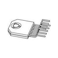
TFA9842J/N1.112 NXP Semiconductors, TFA9842J/N1.112 Datasheet - Page 4

TFA9842J/N1.112
Manufacturer Part Number
TFA9842J/N1.112
Description
Manufacturer
NXP Semiconductors
Datasheet
1.TFA9842JN1.112.pdf
(21 pages)
Specifications of TFA9842J/N1.112
Operational Class
Class-AB
Output Power (typ)
15x1@8Ohm/7.5x2@4OhmW
Audio Amplifier Function
Speaker
Total Harmonic Distortion
0.05@8Ohm@1W%
Single Supply Voltage (typ)
17V
Dual Supply Voltage (typ)
Not RequiredV
Power Supply Requirement
Single
Power Dissipation
35W
Rail/rail I/o Type
No
Single Supply Voltage (min)
9V
Single Supply Voltage (max)
26V
Dual Supply Voltage (min)
Not RequiredV
Dual Supply Voltage (max)
Not RequiredV
Operating Temp Range
-40C to 85C
Operating Temperature Classification
Industrial
Mounting
Through Hole
Pin Count
9
Lead Free Status / RoHS Status
Compliant
Philips Semiconductors
8. Functional description
9397 750 12013
Preliminary data
7.2 Pin description
8.1 Input configuration
8.2 Power amplifier
Table 3:
The input cut-off frequency is:
SE application: R
BTL application: R
As shown in
necessary, so the switch-on delay during charging of the input capacitors can be
minimized. This results in a good low frequency response and good switch-on
behavior.
The power amplifier is a Single-Ended (SE) and/or Bridge-Tied Load (BTL) amplifier
with an all-NPN output stage, capable of delivering a peak output current of 3 A.
Using the TFA9842J as a BTL amplifier offers the following advantages:
Symbol
IN2+
OUT2
CIV
IN1+
GND
SVR
MODE
OUT1+
V
TAB
f
f
f
•
i cut off
i cut off
i cut off
CC
Lower peak value of the supply current
–
–
–
Pin description
=
=
=
Equation 2
---------------------------- -
2
---------------------------------------------------------------- -
2
---------------------------------------------------------------- -
2
Pin
1
2
3
4
5
6
7
8
9
-
60 10
30 10
R
i
= 60 k and C
1
i
i
Rev. 01 — 26 April 2004
= 30 k and C
C
i
3
3
and
1
1
220 10
470 10
Description
input 2
inverted loudspeaker terminal 2
common input voltage decoupling
input 1
ground
half supply voltage decoupling (ripple rejection)
mode selection input (standby, mute and operating)
non inverted loudspeaker terminal 1
supply voltage
back side tab or heats spreader has to be connected to ground
Equation
i
= 220 nF:
i
= 470 nF:
9 –
9 –
2-channel audio amplifier (2 x SE or 1 x BTL)
3, large capacitor values for the inputs are not
=
=
12 Hz
11 Hz
© Koninklijke Philips Electronics N.V. 2004. All rights reserved.
TFA9842J
4 of 21
(1)
(2)
(3)


