320576 TE Connectivity, 320576 Datasheet - Page 7
320576
Manufacturer Part Number
320576
Description
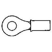
TERMINAL,PIDG R 12-10 5/16
Manufacturer
TE Connectivity
Type
Ring Tongue Terminalr
Series
320r
Specifications of 320576
Rohs Compliant
YES
Stud Size
7.94mm
Wire Gauge
10-12
Body Plating
Tin
Body Material
Copper
Insulation
Nylon
Product Depth (mm)
13.49mm
Product Length (mm)
33.58mm
Color
Yellow
Angle
Straight
Brand/series
PIDG
Contact Plating
Tin
Diameter, Insulation
0.230 "
Insulation Type
Nylon
Length, Overall
1.322 "
Material, Contact
Copper
Primary Type
Ring
Size, Stud
5⁄16 "
Width, Overall
0.531 "
Wire Size
12-10 AWG
Product
Rings
Wire Size (awg)
12-10
Stud / Tab Size
5/16 (M8)
Gender
Female
Contact Material
Copper
Insulation Material
Nylon
Voltage Rating
300 VAC
Terminal Shape
Ring Tongue
Receptacle Style
Straight
Body Style
PIDG
Barrel Type
Closed Barrel
Wire/cable Type
Regular Wire
Insulation Support
Insulation Support
Insulation Diameter (mm [in])
5.84 [.230] Max.
Stud Diameter (mm [in])
7.92 [0.312]
Shape
RING-041
Heavy Duty
No
Finish
Tin
Voltage (vac)
300
Wire/cable Size (cma)
5,180 – 13,100
Wire Range (mm [awg])
3.00-6.00² [12-10]
Tongue Material Thickness (mm [in])
1.07 [0.042]
Class
1 & 2
Government/industry Qualification
Yes
Government/industry Part Number
MS25036-113
Rohs/elv Compliance
RoHS compliant, ELV compliant
Lead Free Solder Processes
Not relevant for lead free process
Rohs/elv Compliance History
Always was RoHS compliant
Packaging Method
Loose Piece
Lead Free Status / RoHS Status
Compliant
Lead Free Status / RoHS Status
Compliant
Available stocks
Company
Part Number
Manufacturer
Quantity
Price


Rev
D
D. Insulation Crimp
The insulation crimp must capture the wire insulation. The wire insulation must not be crimped inside the
wire barrel of the terminal, splice, or end cap. The wire insulation must be inside the metal sleeve to
provide strain relief for the wire. See Figure 5.
E. Bellmouths
There shall be no rear bellmouth. The front bellmouth shall be evident on the top and bottom of the wire
barrel as shown in Figure 5. Also see Figure 11.
F . Flash
There shall be no flash or extruded insulation material visible in the most compressed area of the wire
crimp. See Figure 5.
G. Terminal, Splice, or End Cap Insulation
The insulation of the terminal, splice, or end cap must not be cut or show uneven stress marks or
highlighted marks on the insulation. See Figure 5.
H. Wire Location
I.
The hold of the insulation crimp can be tested by using the bend test which, if successful, indicates that
the hold is not too loose. The bend test must be performed as follows:
1. Terminals shall have the wire ends flush or extended slightly beyond the end of the wire barrel as
shown in Figure 5.
2. Splices shall have the end of the wire located against the wire stop inside the center of the splice.
3. End caps shall have the end of the wire bottomed in the end cap.
Insulation Crimp Check
Bottomed on Stop Inside Center of Splice
Dot Code (1 Dot Shown) is Well Formed and Corresponds With Crimping Chamber of Tooling Used
Wire Flush to End of Wire Barrel or
Wire Insulation Inside Metal Sleeve
But Not Inside Wire Barrel
Detail A
Note:
Splice
No Flash in This Area
Terminal Shown
PIDG Terminals, Splices, and End Caps
Overstress Marks Not
Apparent on Insulation
No Rear Bellmouth
Same Applies to Splice and End Cap
Figure 5
Wire Size Marking
Matches Wire Size
Front Bellmouth Evident
(Top and Bottom of Wire Barrel)
Detail B
Wire Conductor(s) Visible Within This Area
(Except Splice and End Cap, See Detail A
and Detail B)
Wire Bottomed
in End Cap
End Cap
Cutaway Shown for Clarity
114-2157
7
of 14
Related parts for 320576
Image
Part Number
Description
Manufacturer
Datasheet
Request
R

Part Number:
Description:
TERMINAL, SPADE/FORK, #10, CRIMP, BLUE
Manufacturer:
TE Connectivity
Datasheet:

Part Number:
Description:
CIRCULAR INSERT, SOCKET, 30WAY, SOLDER
Manufacturer:
Amphenol Industrial Operations
Datasheet:


Part Number:
Description:
High Speed / Modular Connectors 30P HEADER ASSY
Manufacturer:
TE Connectivity
Datasheet:

Part Number:
Description:
High Speed / Modular Connectors REC 6X005P R/A LT B-PLANE HS3
Manufacturer:
TE Connectivity
Datasheet:

Part Number:
Description:
High Speed / Modular Connectors 2MM HM RCPT 50P R/A AU
Manufacturer:
TE Connectivity
Datasheet:

Part Number:
Description:
High Speed / Modular Connectors 2MM HM RCPT 50P R/A AU
Manufacturer:
TE Connectivity
Datasheet:


Part Number:
Description:
Manufacturer:
TE Connectivity
Datasheet:


Part Number:
Description:
Manufacturer:
TE Connectivity
Datasheet:

Part Number:
Description:
Manufacturer:
TE Connectivity
Datasheet:

Part Number:
Description:
Manufacturer:
TE Connectivity
Datasheet: