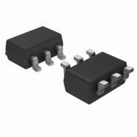
KBMF01SC6 STMicroelectronics, KBMF01SC6 Datasheet - Page 5

KBMF01SC6
Manufacturer Part Number
KBMF01SC6
Description
IC EMI FILTER/LINE TERM SOT23-6
Manufacturer
STMicroelectronics
Series
IPAD™r
Datasheet
1.KBMF01SC6.pdf
(8 pages)
Specifications of KBMF01SC6
Capacitance
150pF
Package / Case
SOT-23-6
Channels
2 Channels
Breakdown Voltage
6 V
Termination Style
SMD/SMT
Power Dissipation Pd
100 mW
Operating Temperature Range
0 C to + 70 C
Lead Free Status / RoHS Status
Lead free / RoHS Compliant
Power (watts)
-
Tolerance
-
Resistance In Ohms
-
Lead Free Status / Rohs Status
Lead free / RoHS Compliant
Other names
497-3712-2
Available stocks
Company
Part Number
Manufacturer
Quantity
Price
Company:
Part Number:
KBMF01SC6
Manufacturer:
SIPEX
Quantity:
16
Part Number:
KBMF01SC6
Manufacturer:
ST
Quantity:
20 000
4. CROSSTALK BEHAVIOR
Figure 7: Crosstalk phenomena
The crosstalk phenomena is due to the coupling between 2 lines. The coupling factor ( 12 or 21 )
increases when the gap across lines decreases, this is the reason why we provide crosstalk
measurements for monolithic device to guarantee negligeable crosstalk between the lines. In the example
above the expected signal on load R
line 2. This phenomenon has to be taken into account when the drivers impose fast digital data or high
frequency analog signals in the disturbing line. The perturbed line will be more affected if it works with low
voltage signal or high load impedance (few k ).
Figure 8: Analog Crosstalk measurements
configuration
Figure 8 gives the measurement circuit for the analog crosstalk application. In figure 9, the curve shows
the effect of the Data line on the CLK line. In usual frequency range of analog signals (up to 100MHz) the
effect on disturbed line is less than -37dB.
21
Vg
V
G1
V
. This part of the V
G1
50
TG OUT
V
G2
DRIVERS
R
G1
TEST BOARD
G1
R
G2
signal represents the effect of the crosstalk phenomenon of the line 1 on the
L2
RF IN
is
2
Line 1
50
Line 2
V
G2
, in fact the real voltage at this point has got an extra value
Figure 9: Typical Analog Crosstalk meas-
urement
crosstalk (dB)
-100
-120
-20
-40
-60
-80
0
RECEIVERS
1
R
L2
R
L1
10
2
V +
F (MHz)
G2
1
V +
21
100
G1
V
G1
12
V
G2
KBMF
1,000
5/8


