CY2XF23FLXCT Cypress Semiconductor Corp, CY2XF23FLXCT Datasheet - Page 4
CY2XF23FLXCT
Manufacturer Part Number
CY2XF23FLXCT
Description
IC XTAL OSC LVDS I2C 6CLCC
Manufacturer
Cypress Semiconductor Corp
Datasheet
1.CY2XF23FLXCT.pdf
(14 pages)
Specifications of CY2XF23FLXCT
Pll
Yes
Input
Crystal
Output
LVDS
Number Of Circuits
1
Ratio - Input:output
1:1
Differential - Input:output
No/Yes
Frequency - Max
690MHz
Divider/multiplier
Yes/No
Voltage - Supply
*
Operating Temperature
*
Mounting Type
Surface Mount
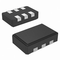
Package / Case
6-CLCC
Frequency
*
Count
*
Operating Supply Voltage (typ)
2.5/3.3
Output Level
LVDS
Symmetry Max
60%
Operating Temp Range
0C to 70C
Screening Level
Commercial
Lead Free Status / RoHS Status
Lead free / RoHS Compliant


Factory-Configured CY2XF23
For ready-to-use devices, the CY2XF23 is available with no field
programming required. Pre-configured devices (see
and Application-Specific Factory
for samples or orders, or a request for a custom configuration
can be made. All requests are submitted to the local Cypress
Field Application Engineer (FAE) or sales representative. After
the request is processed, the user receives a new part number,
samples, and datasheet with the programmed values. This part
number is used for additional sample requests and production
orders. The CY2XF23 is one-time programmable (OTP).
Programming Variables
Output Frequencies
The CY2XF23 is programmed with up to four independent output
frequencies, which are then selected using the I
device can synthesize frequencies to a resolution of 1 part per
million (ppm), but the actual accuracy of the output frequency is
limited by the accuracy of the integrated reference crystal.
The CY2XF23 has an output frequency range of 50 MHz to
690 MHz, but the range is not continuous. The CY2XF23 cannot
generate frequencies in the ranges of 521 MHz to 529 MHz and
596 MHz to 617 MHz.
Industrial versus Commercial Device Performance
Industrial and commercial devices have different internal
crystals. They have a potentially significant impact on
performance levels for applications requiring the lowest possible
phase noise. CyClockWIzard software allows the user to select
between and view the expected performance of both options.
Table 2. Device Programming Variables
Memory Map
Five fields can be written via the I
define the output frequency. As shown in
words is a 6-byte field. When writing to a frequency word, all six
bytes should be written. They may be written either as individual
byte writes, or as a block write. The currently selected frequency
word should not be written to. All four words are symmetrical,
meaning that a 6-byte value that is valid for one word is also valid
for any of the other words, and produces the same frequency.
The fifth field is the select byte, located at byte address 40h. The
value written into the two least significant bits determines the
active frequency word. The other bits of the byte are reserved
and must be written with the values indicated in the table. Users
should never write to any address other than the 25 bytes
described here.
Document Number: 001-53145 Rev. *D
Output frequency 0
Output frequency 1
Output frequency 2
Output frequency 3
Temperature range (commercial or industrial)
Variable
2
Configurations) are available
C bus. Four frequency words
Table
2
3, each of these
C interface. The
PRELIMINARY
Standard
Table 3. Frequency Words
Table 4. Register 40h: Select Byte
Serial Interface Protocol and Timing
The CY2XF23 uses pins SDA and SCLK for an I
operates up to 100 kbits/sec in read or write mode. The
CY2XF23 is always a slave on this bus, meaning that it never
initiates a bus transaction. The basic write protocol is as follows:
Start Bit; 7-bit Device Address (DA); R/W Bit; Slave Clock
Acknowledge (ACK); 8-bit Memory Address (MA); ACK; 8-bit
Data; ACK; 8-bit Data in MA+1 if desired; ACK; 8-bit Data in
MA+2; ACK; and so on, until STOP Bit. The basic serial format
is illustrated in
Device Address
The device address is a 7-bit value. The default serial interface
address is 69H.
Data Valid
Data is valid when the clock is HIGH, and may only be
transitioned when the clock is LOW as illustrated in
Data Frame
Every new data frame is indicated by a start and stop sequence,
as illustrated in
START Sequence - Start frame is indicated by SDA going LOW
when SCLK is HIGH. Every time a start signal is given, the next
8-bit data must be the device address (seven bits) and a R/W bit,
followed by register address (eight bits) and register data (eight
bits).
STOP Sequence - Stop frame is indicated by SDA going HIGH
when SCLK is HIGH. A stop frame frees the bus for writing to
another part on the same bus or writing to another random
register address.
Acknowledge Pulse
During
Acknowledge (ACK) pulse after every eight bits. This is
accomplished by pulling the SDA line LOW during the N*9
cycle as illustrated in
bytes transmitted). After the data packet is sent during read
mode, the master generates the acknowledge.
Bits
7:2
1:0
Frequency
Word
0
1
2
3
000000
User-defined Word select Selects the Frequency
Default Val-
ue (binary)
write
Figure 4
Figure 6
mode,
Byte Addresses
1Ch to 21h
16h to 1Bh
10h to 15h
22h to 27h
Reserved
Figure 7
on page 6.
(hex)
on page 6.
the
Name
CY2XF23
on page 7. (N = the number of
Reserved. Always write this
value.
Word to determine the
output frequency. 00
selects Word 0; 01 selects
Word 1; 10 selects Word 2;
11 selects Word 3.
(Select Byte 40h)
responds
Description
Word Select
CY2XF23
00
01
10
11
Page 4 of 14
2
Figure 5
C bus that
with
th
clock
an
[+] Feedback
Related parts for CY2XF23FLXCT
Image
Part Number
Description
Manufacturer
Datasheet
Request
R

Part Number:
Description:
Manufacturer:
Cypress Semiconductor Corp
Datasheet:
Part Number:
Description:
Manufacturer:
Cypress Semiconductor Corp
Datasheet:
Part Number:
Description:
Manufacturer:
Cypress Semiconductor Corp
Datasheet:
Part Number:
Description:
Manufacturer:
Cypress Semiconductor Corp
Datasheet:
Part Number:
Description:
Manufacturer:
Cypress Semiconductor Corp
Datasheet: