CY2XF24FLXIT Cypress Semiconductor Corp, CY2XF24FLXIT Datasheet - Page 5
CY2XF24FLXIT
Manufacturer Part Number
CY2XF24FLXIT
Description
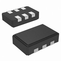
IC XTAL OSC LVPECL I2C 6CLCC
Manufacturer
Cypress Semiconductor Corp
Datasheet
1.CY2XF24FLXCT.pdf
(15 pages)
Specifications of CY2XF24FLXIT
Pll
Yes
Input
Crystal
Output
LVPECL
Number Of Circuits
1
Ratio - Input:output
1:1
Differential - Input:output
No/Yes
Frequency - Max
690MHz
Divider/multiplier
Yes/No
Voltage - Supply
*
Operating Temperature
*
Mounting Type
Surface Mount
Package / Case
6-CLCC
Frequency
*
Count
*
Operating Supply Voltage (typ)
2.5/3.3
Output Level
LVPECL
Symmetry Max
60%
Operating Temp Range
-40C to 85C
Screening Level
Industrial
Lead Free Status / RoHS Status
Lead free / RoHS Compliant


Write Operations
Writing Individual Bytes
A valid write operation must have a full 8-bit register address
after the device address word from the master, which is followed
by an acknowledge bit from the slave (SDA = 0/LOW). The next
eight bits must contain the data word intended for storage. After
the data word is received, the slave responds with another
acknowledge bit (SDA = 0/LOW), and the master must end the
write sequence with a STOP condition.
Writing Multiple Bytes
To write more than one byte at a time, the master does not end
the write sequence with a stop condition. Instead, the master can
send multiple contiguous bytes of data to be stored. After each
byte, the slave responds with an acknowledge bit, just like after
the first byte, and accept data until the acknowledge bit is
responded to by the STOP condition. When receiving multiple
bytes, the CY2XF24 internally increments the register address.
Read Operations
Read operations are initiated the same way as write operations
except that the R/W bit of the slave address is set to ‘1’ (HIGH).
There are three basic read operations: current address read,
random read, and sequential read.
Current Address Read
The CY2XF24 has an onboard address counter that retains 1
more than the address of the last word access. If the last word
written or read was word ‘n’, then a current address read
operation would return the value stored in location ‘n+1’. When
the CY2XF24 receives the slave address with the R/W bit set to
a ‘1’, the CY2XF24 issues an acknowledge and transmits the
8-bit word. The master device does not acknowledge the
transfer, but does generate a STOP condition, which causes the
CY2XF24 to stop transmission.
Document Number: 001-53146 Rev. *D
SCLK
SDA
START
Condition
Figure 3. Data Transfer Sequence on the Serial Bus
Address or
Acknowledge
Valid
PRELIMINARY
Data may
be changed
Random Read
Through random read operations, the master may access any
memory location. To perform this type of read operation, first the
word address must be set. This is accomplished by sending the
address to the CY2XF24 as part of a write operation. After the
word address is sent, the master generates a START condition
following the acknowledge. This terminates the write operation
before any data is stored in the address, but not before the
internal address pointer is set. Next the master reissues the
control byte with the R/W byte set to ‘1’. The CY2XF24 then
issues an acknowledge and transmits the 8-bit word. The master
device does not acknowledge the transfer, but does generate a
STOP condition which causes the CY2XF24 to stop trans-
mission.
Sequential Read
Sequential read operations follow the same process as random
reads except that the master issues an acknowledge instead of
a STOP condition after transmission of the first 8-bit data word.
This action results in an incrementing of the internal address
pointer, and subsequently output of the next 8-bit data word. By
continuing to issue acknowledges instead of STOP conditions,
the master may serially read the entire contents of the slave
device memory. When the internal address pointer points to the
FFh register, after the next increment, the pointer points to the
00h register.
STOP
Condition
CY2XF24
Page 5 of 15
[+] Feedback
Related parts for CY2XF24FLXIT
Image
Part Number
Description
Manufacturer
Datasheet
Request
R

Part Number:
Description:
Manufacturer:
Cypress Semiconductor Corp
Datasheet:
Part Number:
Description:
Manufacturer:
Cypress Semiconductor Corp
Datasheet:
Part Number:
Description:
Manufacturer:
Cypress Semiconductor Corp
Datasheet:
Part Number:
Description:
Manufacturer:
Cypress Semiconductor Corp
Datasheet:
Part Number:
Description:
Manufacturer:
Cypress Semiconductor Corp
Datasheet: