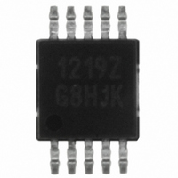
ISL1219IUZ Intersil, ISL1219IUZ Datasheet - Page 4

ISL1219IUZ
Manufacturer Part Number
ISL1219IUZ
Description
IC RTC LP BATT BACK SRAM 10MSOP
Manufacturer
Intersil
Type
Clock/Calendar/NVSRAMr
Specifications of ISL1219IUZ
Memory Size
2B
Time Format
HH:MM:SS (12/24 hr)
Date Format
YY-MM-DD-dd
Interface
I²C, 2-Wire Serial
Voltage - Supply
2.7 V ~ 5.5 V
Operating Temperature
-40°C ~ 85°C
Mounting Type
Surface Mount
Package / Case
10-MSOP, Micro10™, 10-uMAX, 10-uSOP
Clock Format
HH
Clock Ic Type
RTC
Interface Type
I2C, Serial
Memory Configuration
2 X 8
Supply Voltage Range
2.7V To 5.5V
Digital Ic Case Style
MSOP
Rohs Compliant
Yes
Lead Free Status / RoHS Status
Lead free / RoHS Compliant
Available stocks
Company
Part Number
Manufacturer
Quantity
Price
Company:
Part Number:
ISL1219IUZ
Manufacturer:
Intersil
Quantity:
490
Company:
Part Number:
ISL1219IUZ
Manufacturer:
Intersil
Quantity:
222
Part Number:
ISL1219IUZ-T
Manufacturer:
INTERSIL
Quantity:
20 000
I
Power-Down Timing
2
V
V
Hysteresis
V
Cpin
f
t
t
t
t
t
t
t
t
t
t
t
t
t
V
SCL
IN
AA
BUF
LOW
HIGH
SU:STA
HD:STA
SU:DAT
HD:DAT
SU:STO
HD:STO
DH
R
SYMBOL
C Interface Specifications
IL
IH
OL
DD SR-
SYMBOL
SDA and SCL Input Buffer LOW
Voltage
SDA and SCL Input Buffer HIGH
Voltage
SDA and SCL Input Buffer Hysteresis
SDA Output Buffer LOW Voltage,
Sinking 3mA
SDA and SCL Pin Capacitance
SCL Frequency
Pulse Width Suppression Time at
SDA and SCL Inputs
SCL Falling Edge to SDA Output Data
Valid
Time the Bus Must be Free before the
Start of a New Transmission
Clock LOW Time
Clock HIGH Time
START Condition Setup Time
START Condition Hold Time
Input Data Setup Time
Input Data Hold Time
STOP Condition Setup Time
STOP Condition Hold Time
Output Data Hold Time
SDA and SCL Rise Time
V
DD
Negative Slew Rate
PARAMETER
Test Conditions: V
PARAMETER
4
Test Conditions: V
DD
= +2.7 to +5.5V, Temperature = -40°C to +85°C, unless otherwise stated.
V
T
V
Any pulse narrower than the max spec
is suppressed.
SCL falling edge crossing 30% of V
until SDA exits the 30% to 70% of V
window.
SDA crossing 70% of V
STOP condition, to SDA crossing 70%
of V
condition.
Measured at the 30% of V
Measured at the 70% of V
SCL rising edge to SDA falling edge.
Both crossing 70% of V
From SDA falling edge crossing 30%
of V
70% of V
From SDA exiting the 30% to 70% of
V
crossing 30% of V
From SCL falling edge crossing 30%
of V
70% of V
From SCL rising edge crossing 70% of
V
of V
From SDA rising edge to SCL falling
edge. Both crossing 70% of V
From SCL falling edge crossing 30%
of V
70% of V
From 30% to 70% of V
A
DD
IN
DD
DD
= 25°C, f = 1MHz, V
DD
DD
DD
DD
DD
= 0V, V
DD
, to SDA rising edge crossing 30%
= 5V, I
window, to SCL rising edge
.
, until SDA enters the 30% to
during the following START
to SCL falling edge crossing
to SDA entering the 30% to
= +2.7 to +5.5V, Temperature = -40°C to +85°C, unless otherwise specified.
TEST CONDITIONS
DD
DD
DD
OL
OUT
.
CONDITIONS
window.
window.
ISL1219
= 3mA
= 0V
DD.
DD.
DD
DD
DD
DD
DD
.
= 5V,
during a
crossing.
crossing.
DD
.
DD
DD
,
MIN
0.1 x Cb
0.05 x
1300
1300
0.7 x
V
V
20 +
MIN
-0.3
600
600
600
100
600
600
DD
DD
0
0
(Note 5)
TYP
(Note 4)
TYP
MAX
10
V
MAX
0.3 x
V
400
900
900
300
DD
0.3
0.4
10
50
DD
+
UNITS
V/ms
UNITS
kHz
pF
ns
ns
ns
ns
ns
ns
ns
ns
ns
ns
ns
ns
ns
V
V
V
V
August 14, 2006
NOTES
NOTES
FN6314.1
4
7


