DS1315E-33+ Maxim Integrated Products, DS1315E-33+ Datasheet - Page 6

DS1315E-33+
Manufacturer Part Number
DS1315E-33+
Description
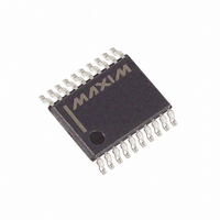
IC T-CHIP PHANTOM 3.3V 20-TSSOP
Manufacturer
Maxim Integrated Products
Type
Phantom Time Chipr
Datasheet
1.DS1315-5.pdf
(23 pages)
Specifications of DS1315E-33+
Time Format
HH:MM:SS:hh (12/24 hr)
Date Format
YY-MM-DD-dd
Interface
Parallel
Voltage - Supply
3 V ~ 3.6 V
Operating Temperature
0°C ~ 70°C
Mounting Type
Surface Mount
Package / Case
20-TSSOP
Lead Free Status / RoHS Status
Lead free / RoHS Compliant
Memory Size
-
DS1315 Phantom Time Chip
Nonvolatile Controller Operation
The operation of the nonvolatile controller circuits within the Time Chip is determined by the level of the
ROM/
select pin. When ROM/
is connected to ground, the controller is set in the RAM mode
RAM
RAM
and performs the circuit functions required to make CMOS RAM and the timekeeping function
nonvolatile. A switch is provided to direct power from the battery inputs or V
to V
with a
CCI
CCO
maximum voltage drop of 0.3 volts. The V
output pin is used to supply uninterrupted power to CMOS
CCO
SRAM. The DS1315 also performs redundant battery control for high reliability. On power-fail, the
battery with the highest voltage is automatically switched to V
. If only one battery is used in the
CCO
system, the unused battery input should be connected to ground.
The DS1315 safeguards the Time Chip and RAM data by power-fail detection and write protection.
Power-fail detection occurs when V
falls below V
which is set by an internal bandgap reference. The
CCI
PF
DS1315 constantly monitors the V
supply pin. When V
is less than V
, power-fail circuitry forces
CCI
CCI
PF
the chip enable output (
) to V
or V
-0.2 volts for external RAM write protection. During
CEO
CCI
BAT
nominal supply conditions,
will track
with a propagation delay. Internally, the DS1315 aborts
CEO
CEI
any data transfer in progress without changing any of the Time Chip registers and prevents future access
until V
exceeds V
. A typical RAM/Time Chip interface is illustrated in Figure 3.
CCI
PF
When the ROM/
pin is connected to V
, the controller is set in the ROM mode. Since ROM is a
RAM
CCO
read-only device that retains data in the absence of power, battery backup and write protection is not
required. As a result, the chip enable logic will force
low when power fails. However, the Time
CEO
Chip does retain the same internal nonvolatility and write protection as described in the RAM mode. A
typical ROM/Time Chip interface is illustrated in Figure 4.
Figure 3. DS1315-to-RAM/Time Chip Interface
6 of 23


