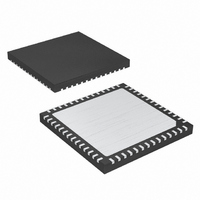
MAX19710ETN+ Maxim Integrated Products, MAX19710ETN+ Datasheet - Page 7

MAX19710ETN+
Manufacturer Part Number
MAX19710ETN+
Description
IC ANLG FRONT END 7.5MSPS 56TQFN
Manufacturer
Maxim Integrated Products
Datasheet
1.MAX19710ETN.pdf
(37 pages)
Specifications of MAX19710ETN+
Number Of Bits
10
Number Of Channels
2
Power (watts)
30mW
Voltage - Supply, Analog
3V
Voltage - Supply, Digital
3V
Package / Case
56-TQFN Exposed Pad
Lead Free Status / RoHS Status
Lead free / RoHS Compliant
ELECTRICAL CHARACTERISTICS (continued)
(V
amplitude = -0.5dBFS, Tx DAC output amplitude = 0dBFS, CM1 = 0, CM0 = 0, differential Rx ADC input, differential Tx DAC output,
C
T
A
CS/WAKE High to DOUT
Active High
CS/WAKE High to DOUT Low
(Aux-ADC Conversion Time)
DOUT Low to CS/WAKE
Setup Time
SCLK Low to DOUT Data Out
CS/WAKE High to DOUT High
Impedance
SERIAL-INTERFACE TIMING CHARACTERISTICS (Figures 6 and 8, Note 2)
Falling Edge of CS/WAKE to Rising
Edge of First SCLK Time
DIN to SCLK Setup Time
DIN to SCLK Hold Time
SCLK Pulse-Width High
SCLK Pulse-Width Low
SCLK Period
SCLK to CS/WAKE Setup Time
CS/WAKE High Pulse Width
MODE-RECOVERY TIMING CHARACTERISTICS (Figure 7)
Shutdown Wake-Up Time
Idle Wake-Up Time
(With CLK)
REFP
DD
(With CLK)
= +25°C.) (Note 1)
= 3V, OV
= C
REFN
PARAMETER
DD
= C
= 1.8V, internal reference (1.024V), C
COM
_______________________________________________________________________________________
= 0.33µF, C
L
< 5pF on all aux-DAC outputs, T
t
SYMBOL
t
WAKE,ST0
WAKE,SD
t
t
CONV
t
t
t
t
CSW
CSS
t
t
t
t
t
CSD
DCS
t
CHZ
t
DS
DH
CH
CP
CS
CD
CL
Bit AD0 set
Bit AD0 set, no averaging, f
CLK divider = 2
Bit AD0, AD10 set
Bit AD0, AD10 set
Bit AD0, AD10 set
From shutdown to Rx mode, ADC settles
to within 1dB SINAD
From shutdown to Tx mode, DAC settles to
within 10 LSB error
From aux-ADC enable to aux-ADC start
conversion
From shutdown to aux-DAC output valid
From shutdown to FD mode, ADC settles
to within 1dB SINAD, DAC settles to within
10 LSB error
Fr om i d l e to Rx m od e, AD C settl es to w i thi n
1d B S IN AD
From idle to Tx mode, DAC settles to 10
LSB error
From idle to FD mode, ADC settles to
within 1dB SINAD, DAC settles to within 10
LSB error
L
10-Bit, 7.5Msps, Full-Duplex
≈ 10pF on all digital outputs, f
CONDITIONS
A
= T
MIN
CLK
to T
MAX
= 7.5MHz,
Analog Front-End
CLK
, unless otherwise noted. Typical values are at
= 7.5MHz (50% duty cycle), Rx ADC input
MIN
10
10
25
25
50
10
80
0
TYP
26.2
200
200
200
500
500
4.3
7.3
5.2
7.3
10
28
MAX
14.5
UNITS
ns
µs
ns
ns
ns
ns
ns
ns
ns
ns
ns
ns
ns
µs
µs
7


