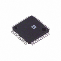
AD9042ASTZ Analog Devices Inc, AD9042ASTZ Datasheet - Page 20

AD9042ASTZ
Manufacturer Part Number
AD9042ASTZ
Description
IC ADC 12BIT 41MSPS 44-TQFP
Manufacturer
Analog Devices Inc
Datasheet
1.AD9042ASTZ.pdf
(24 pages)
Specifications of AD9042ASTZ
Data Interface
Parallel
Number Of Bits
12
Sampling Rate (per Second)
41M
Number Of Converters
3
Power Dissipation (max)
735mW
Voltage Supply Source
Analog and Digital, Dual ±
Operating Temperature
-40°C ~ 85°C
Mounting Type
Surface Mount
Package / Case
44-TQFP, 44-VQFP
Resolution (bits)
12bit
Sampling Rate
41MSPS
Input Channel Type
Single Ended
Supply Voltage Range - Analog
5V
Supply Voltage Range - Digital
5V
Supply Current
119mA
Number Of Elements
1
Resolution
12Bit
Architecture
Pipelined
Sample Rate
41MSPS
Input Polarity
Unipolar
Input Type
Voltage
Rated Input Volt
1.9/2.9V
Differential Input
No
Power Supply Requirement
Single
Single Supply Voltage (typ)
5V
Single Supply Voltage (min)
4.75V
Single Supply Voltage (max)
5.25V
Dual Supply Voltage (typ)
Not RequiredV
Dual Supply Voltage (min)
Not RequiredV
Dual Supply Voltage (max)
Not RequiredV
Power Dissipation
735mW
Differential Linearity Error
±1LSB
Integral Nonlinearity Error
±0.75LSB(Typ)
Operating Temp Range
-40C to 85C
Operating Temperature Classification
Industrial
Mounting
Surface Mount
Pin Count
44
Package Type
LQFP
Input Signal Type
Single-Ended
Lead Free Status / RoHS Status
Lead free / RoHS Compliant
Lead Free Status / RoHS Status
Lead free / RoHS Compliant, Lead free / RoHS Compliant
Available stocks
Company
Part Number
Manufacturer
Quantity
Price
Company:
Part Number:
AD9042ASTZ
Manufacturer:
Analog Devices Inc
Quantity:
10 000
Part Number:
AD9042ASTZ
Manufacturer:
ADI/亚德诺
Quantity:
20 000
AD9042
Assuming that the C/N ratio must be 6 dB or better for accurate
demodulation, one of the eight signals can be reduced by 48.8 dB
before demodulation becomes unreliable. At this point, the
input signal power would be 40.6 μV rms on the ADC input or
−74.8 dBm. Referenced to the antenna, this is −104.8 dBm.
To improve sensitivity, several things can be done. First, the
noise figure of the receiver can be reduced. Because front-end
noise dominates the 0.529 mV rms, each dB reduction in noise
figure translates to an additional dBc of sensitivity. Second,
providing broadband AGC can improve sensitivity by the range
of the AGC. However, the AGC only provides useful
improvements if all in-band signals are kept to an absolute
minimal power level so that AGC can be kept near the
maximum gain.
This noise-limited example does not adequately demonstrate
the true limitations in a wideband receiver. Other limitations
such as SFDR are more restrictive than SNR and noise. Assume
that the ADC has an SFDR specification of −80 dBFS or −76
dBm (full scale = 4 dBm). Also assume that a tolerable carrier-
to-interferer (C/I) (different from C/N) ratio is 18 dB (C/I is the
ratio of signal to in-band interfere). This means that the
minimum signal level is −62 dBFS (−80 plus 18) or −58 dBm.
At the antenna, this is −88 dBm. Therefore, as can be seen,
SFDR (single or multitone) would limit receiver performance in
this example. However, SFDR can be greatly improved through
the use of dither (see Figure 15 and Figure 18). In many cases,
the addition of the out-of-band dither can improve receiver
sensitivity nearly to that limited by thermal noise.
Multitone Performance
Figure 43 shows the AD9042 in a worst-case scenario of four
strong tones spaced fairly close together. In this plot, no dither
was used, and the converter still maintains 85 dBFS of spurious-
free range. As noted in the Overcoming Static Nonlinearities
with Dither section, a modest amount of dither introduced out-
of-band can be used to lower the nonlinear components.
–100
–120
–20
–40
–60
–80
0
dc
ENCODE = 41MSPS
3
Figure 43. Multitone Performance
4.1
6
9
FREQUENCY (MHz)
8.2
7
4
12.3
2
16.4
5
8
20.5
Rev. B | Page 20 of 24
IF SAMPLING, USING THE AD9042 AS A MIX-
DOWN STAGE
Because the performance of the AD9042 extends beyond the
baseband region into the second and third Nyquist zone, the
converter may find many uses as a mix-down converter in both
narrow-band and wideband applications. Many common IF
frequencies exist in this range of frequencies. If the ADC is used
to sample these signals, they are aliased down to baseband during
the sampling process in much the same manner that a mixer
downconverts a signal. For signals in various Nyquist zones, the
following equations may be used to determine the final
frequency after aliasing.
Using the converter to alias down these narrow-band or
wideband signals has many potential benefits. First and
foremost is the elimination of a complete mixer stage, along
with amplifiers, filters, and other devices, reducing cost and
power dissipation.
One common example is the digitization of a 21.4 MHz IF using a
10 MSPS sample clock. Using the equation for the fifth Nyquist
zone, the resultant frequency after sampling is 1.4 MHz. Figure 44
shows performance under these conditions. Even under these
conditions, the AD9042 typically maintains better than 80 dB
SFDR.
f
f
f
f
1NYQUISTS
2NYQUISTS
3NYQUISTS
4NYQUISTS
–100
–120
–20
–40
–60
–80
0
dc
= f
= abs (f
= 2 × (f
= abs (2 × f
8
Figure 44. IF Sampling at 21.4 MHz Input
SAMPLE
7
1
SAMPLE
SAMPLE
− f
SIGNAL
SAMPLE
FREQUENCY (MHz)
− f
− f
8
2
SIGNAL
SIGNAL
6
− f
SIGNAL
2
)
)
ENCODE = 10.0MSPS
AIN = 21.4MHz
3
)
5
3
4
4
5


