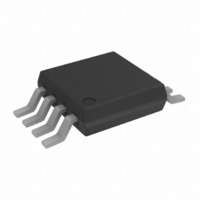
AD7276BRMZ Analog Devices Inc, AD7276BRMZ Datasheet - Page 21

AD7276BRMZ
Manufacturer Part Number
AD7276BRMZ
Description
IC ADC 12BIT 3MSPS HS LP 8MSOP
Manufacturer
Analog Devices Inc
Datasheet
1.AD7278AUJZ-500RL7.pdf
(28 pages)
Specifications of AD7276BRMZ
Data Interface
DSP, MICROWIRE™, QSPI™, Serial, SPI™
Number Of Bits
12
Sampling Rate (per Second)
3M
Number Of Converters
1
Power Dissipation (max)
19.8mW
Voltage Supply Source
Single Supply
Operating Temperature
-40°C ~ 125°C
Mounting Type
Surface Mount
Package / Case
8-TSSOP, 8-MSOP (0.118", 3.00mm Width)
Resolution (bits)
12bit
Sampling Rate
3MSPS
Input Channel Type
Single Ended
Supply Current
5.5mA
Digital Ic Case Style
SOP
No. Of Pins
8
Lead Free Status / RoHS Status
Lead free / RoHS Compliant
For Use With
EVAL-AD7276CBZ - BOARD EVALUATION FOR AD7276
Lead Free Status / RoHS Status
Lead free / RoHS Compliant, Lead free / RoHS Compliant
Available stocks
Company
Part Number
Manufacturer
Quantity
Price
Company:
Part Number:
AD7276BRMZ
Manufacturer:
Analog Devices Inc
Quantity:
135
Part Number:
AD7276BRMZ
Manufacturer:
ADI/亚德诺
Quantity:
20 000
POWER VS. THROUGHPUT RATE
Figure 29 shows the power consumption of the device in
normal mode, in which the part is never powered down. By
using the power-down mode of the AD7276/AD7277/AD7278
when not performing a conversion, the average power consump-
tion of the ADC decreases as the throughput rate decreases.
Figure 30 shows that as the throughput rate is reduced, the
device remains in its power-down state longer, and the average
power consumption over time drops accordingly. For example,
if the AD7276/AD7277/AD7278 are operated in continuous
sampling mode with a throughput rate of 200 kSPS and an SCLK
of 48 MHz (V
down mode between conversions, then the power consumption
is calculated as follows. The power dissipation during normal
operation is 12.6 mW (V
dummy cycle, that is, 333 ns, and the remaining conversion
time is 290 ns, then the AD7276/AD7277/AD7278 can be said
to dissipate 12.6 mW for 623 ns during each conversion cycle. If
the throughput rate is 200 kSPS, then the cycle time is 5 μs and
the average power dissipated during each cycle is 623/5,000 ×
12.6 mW = 1.56 mW. Figure 29 shows the power vs. throughput
rate when using the partial power-down mode between conver-
sions at 3 V. The power-down mode is intended for use with
throughput rates of less than 600 kSPS, because at higher
sampling rates, there is no power saving achieved by using the
power-down mode.
DD
= 3 V) and the devices are placed into power-
DD
= 3 V). If the power-up time is one
Rev. B | Page 21 of 28
7.4
7.2
7.0
6.8
6.6
6.4
6.2
6.0
5.8
5.6
5.4
5.2
5.0
4.8
4.6
4.4
4.2
4.0
3.8
3.6
3.4
3.2
3.0
8.0
7.5
7.0
6.5
6.0
5.5
5.0
4.5
4.0
3.5
3.0
2.5
2.0
1.5
1.0
0.5
Figure 30. Power vs. Throughput Partial Power-Down Mode
0
0
0
Figure 29. Power vs. Throughput Normal Mode
200
400
200
600
AD7276/AD7277/AD7278
THROUGHPUT (kSPS)
THROUGHPUT (kSPS)
800
400
1000 1200 1400 1600 1800
50MHz SCLK
600
800
VARIABLE
SCLK
V
DD
= 3V
2000
1000


