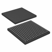
AD6654BBC Analog Devices Inc, AD6654BBC Datasheet - Page 46

AD6654BBC
Manufacturer Part Number
AD6654BBC
Description
IC ADC 14BIT W/6CH RSP 256CSPBGA
Manufacturer
Analog Devices Inc
Datasheet
1.AD6654CBCZ.pdf
(88 pages)
Specifications of AD6654BBC
Number Of Bits
14
Sampling Rate (per Second)
92.16M
Data Interface
Serial, Parallel
Number Of Converters
1
Power Dissipation (max)
2.5W
Voltage Supply Source
Analog and Digital
Operating Temperature
-25°C ~ 85°C
Mounting Type
Surface Mount
Package / Case
256-CSPBGA
Lead Free Status / RoHS Status
Contains lead / RoHS non-compliant
Available stocks
Company
Part Number
Manufacturer
Quantity
Price
Company:
Part Number:
AD6654BBC
Manufacturer:
AD
Quantity:
13 888
Company:
Part Number:
AD6654BBC
Manufacturer:
ADI
Quantity:
280
Company:
Part Number:
AD6654BBC
Manufacturer:
Analog Devices Inc
Quantity:
10 000
Part Number:
AD6654BBC
Manufacturer:
ADI/亚德诺
Quantity:
20 000
Company:
Part Number:
AD6654BBCZ
Manufacturer:
ADI
Quantity:
853
Company:
Part Number:
AD6654BBCZ
Manufacturer:
Analog Devices Inc
Quantity:
10 000
AD6654
PROGRAMMING CRCF REGISTERS FOR AN
ASYMMETRICAL FILTER
To program the CRCF registers for an asymmetrical filter:
1.
2.
3.
4.
5.
6.
Note that each write or read access increments the internal
RAM address. Therefore, all coefficients should be read first
before reading them back. Also, for debugging purposes, each
RAM address can be written individually by making the start
and stop addresses the same. Therefore, to program one RAM
location, the user writes the address of the RAM location to
both the start and stop address registers, and then writes the
coefficient memory register.
Write NTAPS – 1 in the CRCF taps register, where NTAPS
is the number of filter taps. The absolute maximum value
for NTAPS is 64 in asymmetrical filter mode.
Write 0 for the CRCF coefficient offset register.
Write 0 for the symmetrical filter bit in the CRCF control
register.
In the CRCF start address register, write the start address
for the coefficient RAM, typically equal to the coefficient
offset register.
In the CRCF stop address register, write the stop address
for the coefficient RAM, typically equal to the following:
Write all coefficients in reverse order (start with last
coefficient) to the CRCF coefficient memory register. In
8 bit microport mode or serial port mode, write the lower
byte of the memory register first and then the higher byte.
In 16-bit microport mode, write the lower 16-bits of the
CRCF memory register first and then the high four bits.
After each write access to the CRCF coefficient memory
register, the internal RAM address is incremented starting
with the start address and ending with the stop address.
Coefficient Offset + NTAPS – 1
Rev. 0 | Page 46 of 88
PROGRAMMING CRCF REGISTERS FOR A
SYMMETRICAL FILTER
To program the CRCF registers for a symmetrical filter:
1.
2.
3.
4.
5.
6.
Note that each write or read access increments the internal
RAM address. Therefore, all coefficients should be read first
before reading them back. Also, for debugging purposes, each
RAM address can be written individually by making the start
and stop addresses the same. Therefore, to program one RAM
location, the user writes the address of the RAM location to
both the start and stop address registers, and then writes the
coefficient memory register.
Write NTAPS – 1 in the CRCF taps register, where NTAPS
is the number of filter taps. The absolute maximum value
for NTAPS is 128 in symmetrical filter mode.
Write ceil (64 – NTAPS/2) for the CRCF coefficient offset
register, where the ceil function takes the closest integer
greater than or equal to the argument.
Write 1 for the symmetrical filter bit in the CRCF control
register.
In the CRCF start address register, write the start address
for the coefficient RAM, typically equal to the coefficient
offset register.
In the CRCF stop address register, write the stop address
for the coefficient RAM, typically equal to
ceil (NTAPS/2) – 1.
Write all coefficients to the CRCF coefficient memory
register, starting with middle of the filter and working
towards the end of the filter. When coefficients are
numbered 0 to NTAPS – 1, the middle coefficient is given
by the coefficient number ceil (NTAPS/2). In 8-bit
microport mode or serial port mode, write the lower byte
of the memory register first and then the higher byte. In
16-bit microport mode, write the lower 16-bits of the
CRCF memory register first and then the high four bits.
After each write access to the CRCF coefficient memory
register, the internal RAM address is incremented starting
with the start address and ending with the stop address.


