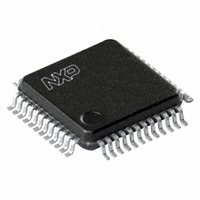
TDA9965HL/C3,118 NXP Semiconductors, TDA9965HL/C3,118 Datasheet - Page 11

TDA9965HL/C3,118
Manufacturer Part Number
TDA9965HL/C3,118
Description
IC ADC 12-BIT 30MSPS 48-LQFP
Manufacturer
NXP Semiconductors
Type
CCD (Charged Coupled Device)r
Datasheet
1.TDA9965HLC3118.pdf
(22 pages)
Specifications of TDA9965HL/C3,118
Resolution (bits)
12 b
Sampling Rate (per Second)
30M
Data Interface
Serial
Voltage Supply Source
Analog and Digital
Voltage - Supply
4.75 V ~ 5.25 V
Operating Temperature
-20°C ~ 75°C
Mounting Type
Surface Mount
Package / Case
48-LQFP
Lead Free Status / RoHS Status
Lead free / RoHS Compliant
Other names
568-3612-2
935272592118
TDA9965HLGB-T
935272592118
TDA9965HLGB-T
Available stocks
Company
Part Number
Manufacturer
Quantity
Price
Company:
Part Number:
TDA9965HL/C3,118
Manufacturer:
NXP Semiconductors
Quantity:
10 000
Philips Semiconductors
Table 1 Serial interface programming
Notes
1. PGA gain register must always be refreshed after clamp code register content has been changed.
2. When pin CLPADC = HIGH (SD1 = 1; serial interface), the ADC input is clamped to the voltage level of V
When the power supplies increase from zero to V
Table 2 Standby selection
Note
1. In case an external regulator is used, it has to be switched off in standby mode in order to avoid an extra power
2004 Jul 05
Cut-off frequency of the CTH circuit is set to: code f
PGA gain control is set to: code G
Clamp code of the ADC is set to: code ADC
SHP and SHD sample on HIGH level; CLKADC activated with rising edge
CLPOB and CLPADC activated on HIGH level.
12-bit, 5.0 V, 30 Msps analog-to-digital
interface for CCD cameras
is connected to ground via a capacitor.
consumption of the TDA9965.
A1
0
0
1
1
ADDRESS BITS
PIN STDBY
HIGH
LOW
A0
0
1
0
1
PGA
clamp reference of ADC (SD0 to SD9), note 1
cut-off frequency of CTH (SD0 to SD3)
PGA gain control (SD0 to SD9)
edge control for pulses SHP, SHD, CLPOB, CLPADC and CLKADC (note 2):
= 0
SD0 = 1, SHP and SHD sample on LOW level
SD1 = 1, CLPADC and CLPOB activated on HIGH level
SD2 = 1, CLKADC activated with rising edge
CLP
DATA BITS SD9 to SD0
CC
= 0
, the init-on-power block initializes the circuit as follows:
co(CTH)
logic 0
active
11
= 0
SDATA BITS SD0 to SD9
4 mA (typical); note 1
84 mA (typical)
I
CCA
Product specification
+ I
CCD
TDA9965
ref
. Pin V
ref


