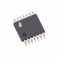
X95820WV14I-2.7 Intersil, X95820WV14I-2.7 Datasheet - Page 6

X95820WV14I-2.7
Manufacturer Part Number
X95820WV14I-2.7
Description
IC XDCP DUAL 256TAP 10K 14-TSSOP
Manufacturer
Intersil
Series
XDCP™r
Datasheet
1.X95820WV14IZ-2.7T1.pdf
(12 pages)
Specifications of X95820WV14I-2.7
Taps
256
Resistance (ohms)
10K
Number Of Circuits
2
Temperature Coefficient
45 ppm/°C Typical
Memory Type
Non-Volatile
Interface
I²C, 2-Wire Serial
Voltage - Supply
2.7 V ~ 5.5 V
Operating Temperature
-40°C ~ 85°C
Mounting Type
Surface Mount
Package / Case
14-TSSOP
Resistance In Ohms
10K
Number Of Elements
2
# Of Taps
256
Resistance (max)
10KOhm
Power Supply Requirement
Single
Interface Type
Serial (I2C)
Single Supply Voltage (typ)
3.3V
Dual Supply Voltage (typ)
Not RequiredV
Single Supply Voltage (min)
2.7V
Single Supply Voltage (max)
5.5V
Dual Supply Voltage (min)
Not RequiredV
Dual Supply Voltage (max)
Not RequiredV
Operating Temp Range
-40C to 85C
Operating Temperature Classification
Industrial
Mounting
Surface Mount
Pin Count
14
Package Type
TSSOP
Lead Free Status / RoHS Status
Contains lead / RoHS non-compliant
NOTES:
Typical Performance Curves
10. Roffset = R
12. RINL = [R
13. R
14.
15. This parameter is not 100% tested.
16. t
11. RDNL = (R
1. Typical values are for T
2. LSB: [V(RW)
3. ZS error = V(RW)
4. FS error = [V(RW)
5. DNL = [V(RW)
6. INL = [V(RW)
7. V
8.
9. MI =
FIGURE 1. WIPER RESISTANCE vs TAP POSITION
TC
160
140
120
100
incremental voltage when changing from one tap to an adjacent tap.
for i = 16 to 240 decimal, T = -40°C to 85°C. Max( ) is the maximum value of the wiper voltage and Min ( ) is the minimum value of the wiper
voltage over the temperature range.
Roffset = R
for i = 32 to 255, T = -40°C to 85°C. Max( ) is the maximum value of the resistance and Min ( ) is the minimum value of the resistance over the
temperature range.
valid STOP condition at the end of a Write sequence of a I
write cycle.
TC
WC
80
60
40
20
MATCH
MATCH
0
V
R
0
is the minimum cycle time to be allowed for any non-volatile Write by the user, unless Acknowledge Polling is used. It is the time from a
|
=
R
=
255
V
--------------------------------------------------------------------------------------------- -
[
V
Max V RW
--------------------------------------------------------------- -
[
CC
= [V(RWx)
= (R
Max Ri
CC
i
Max V RW
[
- (MI • i) - R
Max Ri
[ I(RW) = V
i
0
255
- R
- R
= 2.7, T = -40°C
255
/ MI, when measuring between RW and RL.
= 5.5, T = -40°C
i
(
i,x
i
(
50
– (i • LSB – V(RW)
0
(
/ MI, when measuring between RW and RH.
i-1
- V(RW)
|
(
(
- R
- V(RW)
/ 255. R
) / MI, for i = 32 to 255.
0
(
)
255
+
/ LSB.
) Min Ri
i,y
i
TAP POSITION (DECIMAL)
–
- V(RWy)
Min Ri
)
)
i
- V
CC
)
)
0
/ MI, for i = 0 to 255, x = 0 to 1 and y = 0 to 1.
A
i
i-1
] / MI, for i = 32 to 255.
+
) Min V RW
255
0
CC
(
= 25°C and 3.3V supply voltage.
100
/R
–
Min V RW
] / LSB-1, for i = 1 to 255. i is the DCP register setting.
] / 255. V(RW)
(
TOTAL
] / LSB.
)
and R
V
6
] 2 ⁄
)
i
(
CC
] / LSB, for i = 0 to 255, x = 0 to 1 and y = 0 to 1.
V
]
(
CC
(
= 2.7, T = 85°C
0
×
(
)]/LSB for i = 1 to 255.
0
] FOR 50kΩ (U)
= 5.5, T = 25°C
---------------- -
125°C
are the measured resistances for the DCP register set to FF hex and 00 hex respectively.
150
10
)
i
)
)
6
i
] 2 ⁄
255
)
V
V
and V(RW)
×
CC
CC
---------------- -
125°C
10
200
= 2.7, T = 25°C
= 5.5, T = 85°C
6
0
are V(RW) for the DCP register set to FF hex and 00 hex respectively. LSB is the
2
250
C serial interface Write operation, to the end of the self-timed internal non-volatile
X95820
1.8
1.6
1.4
1.2
1.0
0.8
0.6
0.4
0.2
0.0
2.7
FIGURE 2. STANDBY I
3.2
25°C
-40°C
3.7
V
CC
4.2
(V)
CC
vs V
4.7
CC
85°C
July 18, 2006
5.2
FN8212.2


