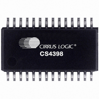
CS4398-CZZ Cirrus Logic Inc, CS4398-CZZ Datasheet - Page 3

CS4398-CZZ
Manufacturer Part Number
CS4398-CZZ
Description
IC DAC 120DB 192KHZ W/VC 28TSSOP
Manufacturer
Cirrus Logic Inc
Datasheet
1.CS4398-CZZ.pdf
(46 pages)
Specifications of CS4398-CZZ
Package / Case
28-TSSOP
Number Of Bits
24
Data Interface
Serial
Number Of Converters
2
Voltage Supply Source
Analog and Digital
Power Dissipation (max)
340mW
Operating Temperature
-10°C ~ 70°C
Mounting Type
Surface Mount
Conversion Rate
216 KSPS
Resolution
24 bit
Interface Type
Serial
Operating Supply Voltage
5 V
Operating Temperature Range
+ 70 C
Maximum Power Dissipation
340 mW
Mounting Style
SMD/SMT
Number Of Dac Outputs
2
Lead Free Status / RoHS Status
Lead free / RoHS Compliant
For Use With
598-1155 - BOARD EVAL FOR CS4398 DAC
Settling Time
-
Lead Free Status / Rohs Status
Lead free / RoHS Compliant
Other names
598-1067-5
Available stocks
Company
Part Number
Manufacturer
Quantity
Price
Company:
Part Number:
CS4398-CZZ
Manufacturer:
CIRRUS
Quantity:
7 885
Part Number:
CS4398-CZZ
Manufacturer:
CIRRUS
Quantity:
20 000
Part Number:
CS4398-CZZR
Manufacturer:
CIRRUS
Quantity:
20 000
DS568F1
TABLE OF CONTENTS
1. PINOUT DRAWING ................................................................................................................. 6
2. CHARACTERISTICS AND SPECIFICATIONS ........................................................................ 8
3. TYPICAL CONNECTION DIAGRAM
4. APPLICATIONS ..................................................................................................................... 20
5. CONTROL PORT INTERFACE ............................................................................................. 25
8. PARAMETER DEFINITIONS .................................................................................................. 39
9. REFERENCES ........................................................................................................................ 39
10. PACKAGE DIMENSIONS .................................................................................................... 40
11. APPENDIX
SPECIFIED OPERATING CONDITIONS ................................................................................. 8
ABSOLUTE MAXIMUM RATINGS ........................................................................................... 8
ANALOG CHARACTERISTICS................................................................................................ 9
COMBINED INTERPOLATION & ON-CHIP ANALOG FILTER RESPONSE ........................ 10
COMBINED INTERPOLATION & ON-CHIP ANALOG FILTER RESPONSE ........................ 11
DSD COMBINED DIGITAL AND ON-CHIP ANALOG FILTER RESPONSE.......................... 11
SWITCHING CHARACTERISTICS ........................................................................................ 12
SWITCHING CHARACTERISTICS - DSD ............................................................................. 14
SWITCHING CHARACTERISTICS - CONTROL PORT - I²C FORMAT ................................ 15
SWITCHING CHARACTERISTICS - CONTROL PORT - SPI™ FORMAT............................ 16
DC ELECTRICAL CHARACTERISTICS ............................................................................... 17
DIGITAL INTERFACE SPECIFICATIONS ............................................................................. 18
4.1 Grounding and Power Supply Decoupling ....................................................................... 20
4.2 Analog Output and Filtering ............................................................................................. 20
4.3 The MUTEC Outputs ....................................................................................................... 20
4.4 Oversampling Modes ....................................................................................................... 21
4.5 Master and Serial Clock Ratios ....................................................................................... 21
4.6 Stand-Alone Mode Settings ............................................................................................. 22
4.7 Control Port Mode ........................................................................................................... 23
5.1 Memory Address Pointer (MAP) ...................................................................................... 25
5.2 Enabling the Control Port ................................................................................................ 25
5.3 Format Selection ............................................................................................................. 25
5.4 I²C Format ....................................................................................................................... 25
5.5 SPI Format ...................................................................................................................... 26
7.1 Chip ID - Register 01h ..................................................................................................... 29
7.2 Mode Control 1 - Register 02h ........................................................................................ 29
7.3 Volume Mixing and Inversion Control - Register 03h ...................................................... 30
7.4 Mute Control - Register 04h ............................................................................................ 33
7.5 Channel A Volume Control - Register 05h ....................................................................... 34
7.6 Channel B Volume Control - Register 06h ....................................................................... 34
7.7 Ramp and Filter Control - Register 07h ........................................................................... 35
7.8 Misc. Control - Register 08h ............................................................................................ 37
7.9 Misc. Control - Register 09h ............................................................................................ 38
10.1 28-TSSOP ..................................................................................................................... 40
THERMAL CHARACTERISTICS AND SPECIFICATIONS ................................................... 40
....................................................................................................................... 41
.................................................................................. 19
CS4398
3


