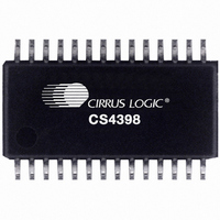
CS4398-CZZ Cirrus Logic Inc, CS4398-CZZ Datasheet - Page 33

CS4398-CZZ
Manufacturer Part Number
CS4398-CZZ
Description
IC DAC 120DB 192KHZ W/VC 28TSSOP
Manufacturer
Cirrus Logic Inc
Datasheet
1.CS4398-CZZ.pdf
(46 pages)
Specifications of CS4398-CZZ
Package / Case
28-TSSOP
Number Of Bits
24
Data Interface
Serial
Number Of Converters
2
Voltage Supply Source
Analog and Digital
Power Dissipation (max)
340mW
Operating Temperature
-10°C ~ 70°C
Mounting Type
Surface Mount
Conversion Rate
216 KSPS
Resolution
24 bit
Interface Type
Serial
Operating Supply Voltage
5 V
Operating Temperature Range
+ 70 C
Maximum Power Dissipation
340 mW
Mounting Style
SMD/SMT
Number Of Dac Outputs
2
Lead Free Status / RoHS Status
Lead free / RoHS Compliant
For Use With
598-1155 - BOARD EVAL FOR CS4398 DAC
Settling Time
-
Lead Free Status / Rohs Status
Lead free / RoHS Compliant
Other names
598-1067-5
Available stocks
Company
Part Number
Manufacturer
Quantity
Price
Company:
Part Number:
CS4398-CZZ
Manufacturer:
CIRRUS
Quantity:
7 885
Part Number:
CS4398-CZZ
Manufacturer:
CIRRUS
Quantity:
20 000
Part Number:
CS4398-CZZR
Manufacturer:
CIRRUS
Quantity:
20 000
DS568F1
7.4
7.4.1
7.4.2
7.4.3
7.4.4
PAMUTE
1
7
Mute Control - Register 04h
PCM Auto-mute (PAMUTE) Bit 7
Function:
When set to 1 (default), the Digital-to-Analog converter output will mute following the reception of 8192
consecutive audio samples of static 0 or -1. A single sample of non-static data will release the mute. De-
tection and muting is done independently for each channel. The quiescent voltage on the output will be
retained, and the Mute Control pin will go active during the mute period.
When set to 0, this function is disabled.
DSD Auto-mute (DAMUTE) Bit 6
Function:
When set to 1 (default), the Digital-to-Analog converter output will mute following the reception of 256 re-
peated 8-bit DSD mute patterns (as defined in the SACD specification).
A single bit not fitting the repeated mute pattern (mentioned above) will release the mute. Detection and
muting is done independently for each channel. The quiescent voltage on the output will be retained, and
the Mute Control pin will go active during the mute period.
When set to 0, this function is disabled.
AMUTEC = BMUTEC (MUTEC A=B) Bit 5
Function:
When set to 0 (default) the AMUTEC and BMUTEC pins operate independently.
When set to 1, the individual controls for AMUTEC and BMUTEC are internally connected through an
AND gate prior to the output pins. Therefore, the external AMUTEC and BMUTEC pins will go active only
when the requirements for both AMUTEC and BMUTEC are valid.
A Channel Mute (MUTE_A) Bit 4
B Channel Mute (MUTE_B) Bit 3
Function:
When set to 1, the Digital-to-Analog converter output will mute. The quiescent voltage on the output will
be retained. The muting function is effected, similar to attenuation changes, by the Soft and Zero Cross
bits in the Volume and Mixing Control register. The corresponding MUTEC pin will go active following any
ramping due to the soft and zero cross function.
When set to 0 (default), this function is disabled.
DAMUTE
6
1
MUTEC A=B
5
0
MUTE_A
0
4
MUTE_B
3
0
Reserved
2
0
MUTEP1
0
1
MUTEP0
CS4398
0
0
33


