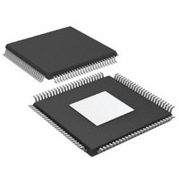
AD9785BSVZ Analog Devices Inc, AD9785BSVZ Datasheet - Page 38

AD9785BSVZ
Manufacturer Part Number
AD9785BSVZ
Description
IC DAC 12BIT 800MSPS 100TQFP
Manufacturer
Analog Devices Inc
Series
TxDAC®r
Datasheet
1.AD9785BSVZ.pdf
(64 pages)
Specifications of AD9785BSVZ
Data Interface
Serial
Number Of Bits
12
Number Of Converters
2
Voltage Supply Source
Analog and Digital
Power Dissipation (max)
450mW
Operating Temperature
-40°C ~ 85°C
Mounting Type
Surface Mount
Package / Case
100-TQFP Exposed Pad, 100-eTQFP, 100-HTQFP, 100-VQFP
Resolution (bits)
12bit
Sampling Rate
800MSPS
Input Channel Type
Parallel
Digital Ic Case Style
QFP
No. Of Pins
100
Operating Temperature Range
-40°C To +85°C
Lead Free Status / RoHS Status
Lead free / RoHS Compliant
Settling Time
-
Lead Free Status / RoHS Status
Lead free / RoHS Compliant, Lead free / RoHS Compliant
Available stocks
Company
Part Number
Manufacturer
Quantity
Price
Company:
Part Number:
AD9785BSVZ
Manufacturer:
Analog Devices Inc
Quantity:
135
Company:
Part Number:
AD9785BSVZ
Manufacturer:
Analog Devices Inc
Quantity:
10 000
Company:
Part Number:
AD9785BSVZRL
Manufacturer:
Analog Devices Inc
Quantity:
10 000
AD9785/AD9787/AD9788
DIGITAL DATAPATH
The AD9785/AD9787/AD9788 digital datapath consists of
three 2× half-band interpolation filters, a quadrature modulator,
and an inverse sinc filter. A 32-bit NCO provides the sine and
cosine carrier signals required for the quadrature modulator.
INTERPOLATION FILTERS
The AD9785/AD9787/AD9788 contain three half-band filters
that can be bypassed. This allows the device to operate with 2×,
4×, or 8× interpolation rates, or without interpolation. The
interpolation filters have a linear phase response. The coefficients
of the low-pass filters are given in Table 28, Table 29, and
Table 30. Spectral plots for the filter responses are shown in
Figure 55, Figure 56, and Figure 57.
In 2×, 4×, or 8× interpolation mode, the usable bandwidth of
the interpolation filter is 80% of the complex input data rate.
The usable bandwidth has a pass-band ripple of less than
0.0005 dB and a stop-band attenuation of greater than 85 dB.
The center frequency of the interpolation filter is set by the
NCO frequency tuning word (Register 0x0A, Bits [31:0]), so
baseband input signals are always centered in the interpolation
filter pass band.
Figure 55. 2× Interpolation, Low-Pass Response to ±4× Input Data Rate
–100
–10
–20
–30
–40
–50
–60
–70
–80
–90
10
0
–4
–3
(Dotted Lines Indicate 1 dB Roll-Off)
–2
f
OUT
–1
(×
Input Data Rate)
0
1
2
3
4
Rev. A | Page 38 of 64
Figure 56. 4× Interpolation, Low-Pass Response to ±4× Input Data Rate
Figure 57. 8× Interpolation, Low-Pass Response to ±4× Input Data Rate
–100
–100
–10
–20
–30
–40
–50
–60
–70
–80
–90
–10
–20
–30
–40
–50
–60
–70
–80
–90
10
10
0
0
–4
–4
–3
–3
(Dotted Lines Indicate 1 dB Roll-Off)
(Dotted Lines Indicate 1 dB Roll-Off)
–2
–2
f
f
OUT
OUT
–1
–1
(×
(×
Input Data Rate)
Input Data Rate)
0
0
1
1
2
2
3
3
4
4


