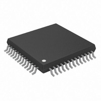
AD5390BSTZ-5 Analog Devices Inc, AD5390BSTZ-5 Datasheet - Page 28

AD5390BSTZ-5
Manufacturer Part Number
AD5390BSTZ-5
Description
IC DAC 14BIT I2C 16CH 52-LQFP
Manufacturer
Analog Devices Inc
Specifications of AD5390BSTZ-5
Data Interface
I²C, Serial
Design Resources
8 to 16 Channels of Programmable Voltage with Excellent Temperature Drift Performance Using AD5390/1/2 (CN0029) AD5390/91/92 Channel Monitor Function (CN0030)
Settling Time
8µs
Number Of Bits
14
Number Of Converters
16
Voltage Supply Source
Single Supply
Power Dissipation (max)
35mW
Operating Temperature
-40°C ~ 85°C
Mounting Type
Surface Mount
Package / Case
52-LQFP
Resolution (bits)
14bit
Sampling Rate
125kSPS
Input Channel Type
Serial
Supply Voltage Range - Analogue
4.5V To 5.5V
Supply Voltage Range - Digital
2.7V To 5.5V
Lead Free Status / RoHS Status
Lead free / RoHS Compliant
For Use With
EVAL-AD5390EBZ - BOARD EVALUATION FOR AD5390
Lead Free Status / RoHS Status
Lead free / RoHS Compliant, Lead free / RoHS Compliant
Available stocks
Company
Part Number
Manufacturer
Quantity
Price
Company:
Part Number:
AD5390BSTZ-5
Manufacturer:
Analog Devices Inc
Quantity:
10 000
AD5390/AD5391/AD5392
I
There are three specific modes in which data can be written to
the AD539x family of DACs.
4-BYTE MODE
When writing to the AD539x DACs, begin with an address byte
(R/W = 0), after which the DAC acknowledges that it is pre-
pared to receive data by pulling SDA low. The address byte is
followed by the pointer byte; this addresses the specific channel
2
C WRITE OPERATION
SCL
SDA
SCL
SDA
CONDITION
MASTER
START
BY
REG1
1
REG0
0
MSB
1
MOST SIGNIFICANT DATA BYTE
ADDRESS BYTE
0
1
AD1
Figure 33. The 4-Byte Mode I
AD0
LSB
R/W
CONVERTER
CONVERTER
Rev. A | Page 28 of 44
ACK
BY
ACK
BY
MSB
MSB
0
2
C Write Operation
in the DAC to be addressed and is also acknowledged by the
DAC. Address Bits A3 to A0 address all channels on the
AD5390/AD5391. Address Bits A2 to A0 address all channels on
the AD5392. Address Bit A3 is a zero on the AD5392. Two bytes
of data then are written to the DAC, as shown in Figure 33. A
STOP condition follows. This lets the user update a single
channel within the AD539x at any time and requires four bytes
of data to be transferred from the master.
0
LEAST SIGNIFICANT DATA BYTE
0
POINTER BYTE
0
A3
A2
A1
A0
CONVERTER
CONVERTER
LSB
ACK
ACK
BY
BY
CONDITION
MASTER
STOP
BY


