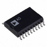
AD7302BR Analog Devices Inc, AD7302BR Datasheet - Page 6

AD7302BR
Manufacturer Part Number
AD7302BR
Description
IC DAC 8BIT DUAL 2.7V 20-SOIC
Manufacturer
Analog Devices Inc
Datasheet
1.AD7302BRUZ.pdf
(16 pages)
Specifications of AD7302BR
Mounting Type
Surface Mount
Rohs Status
RoHS non-compliant
Settling Time
1.2µs
Number Of Bits
8
Data Interface
Parallel
Number Of Converters
2
Voltage Supply Source
Single Supply
Power Dissipation (max)
24.8mW
Operating Temperature
-40°C ~ 105°C
Package / Case
20-SOIC (7.5mm Width)
Resolution (bits)
8bit
No. Of Pins
20
Update Rate
0.833MSPS
Peak Reflow Compatible (260 C)
No
Supply Voltage
5.5V
No. Of Bits
8 Bit
Leaded Process Compatible
No
Lead Free Status / RoHS Status
Contains lead / RoHS non-compliant
Available stocks
Company
Part Number
Manufacturer
Quantity
Price
Part Number:
AD7302BR
Manufacturer:
ADI/亚德诺
Quantity:
20 000
Company:
Part Number:
AD7302BRU
Manufacturer:
AD
Quantity:
4 130
Part Number:
AD7302BRUZ
Manufacturer:
ADI/亚德诺
Quantity:
20 000
Company:
Part Number:
AD7302BRZ
Manufacturer:
Maxim
Quantity:
25
Part Number:
AD7302BRZ
Manufacturer:
ADI/亚德诺
Quantity:
20 000
Part Number:
AD7302BRZ-REEL
Manufacturer:
ADI/亚德诺
Quantity:
20 000
TERMINOLOGY
INTEGRAL NONLINEARITY
For the DACs, relative accuracy or endpoint nonlinearity is a
measure of the maximum deviation, in LSBs, from a straight
line passing through the endpoints of the DAC transfer function.
A graphical representation of the transfer curve is shown in
Figure 14.
DIFFERENTIAL NONLINEARITY
Differential Nonlinearity is the difference between the measured
change and the ideal 1 LSB change between any two adjacent
codes. A specified differential nonlinearity of 1 LSB maximum
ensures monotonicity.
ZERO CODE ERROR
Zero Code Error is the measured output voltage from V
either DAC when zero code (all zeros) is loaded to the DAC
latch. It is due to a combination of the offset errors in the DAC
and output amplifier. Zero scale error is expressed in LSBs.
GAIN ERROR
This is a measure of the span error of the DAC. It is the deviation
in slope of the DAC transfer characteristic from ideal, expressed
as a percent of the full-scale value. It includes full-scale errors
but not offset errors.
DIGITAL-TO-ANALOG GLITCH IMPULSE
Digital-to-Analog Glitch Impulse is the impulse injected into the
analog output when the digital inputs change state with the
DAC selected and the LDAC used to update the DAC. It is
normally specified as the area of the glitch in nV-s and is
measured when the digital input code is changed by 1 LSB at
the major carry transition.
AD7302
OUT
of
–6–
DIGITAL FEEDTHROUGH
Digital Feedthrough is a measure of the impulse injected into
the analog output of a DAC from the digital inputs of the same
DAC, but is measured when the DAC is not updated. It is
specified in nV-s and measured with a full-scale code change on
the data bus, i.e., from all 0s to all 1s and vice versa.
DIGITAL CROSSTALK
Digital Crosstalk is the glitch impulse transferred to the output
of one converter due to a digital code change to another DAC.
It is specified in nV-s.
ANALOG CROSSTALK
Analog Crosstalk is a change in output of any DAC in response
to a change in the output of the other DAC. It is measured in
LSBs.
POWER SUPPLY REJECTION RATIO (PSRR)
This specification indicates how the output of the DAC is
affected by changes in the power supply voltage. Power supply
rejection ratio is quoted in terms of % change in output per %
change in V
10%.
DD
for full-scale output of the DAC. V
DD
is varied
REV. 0


