AD9779BSVZ Analog Devices Inc, AD9779BSVZ Datasheet - Page 45
AD9779BSVZ
Manufacturer Part Number
AD9779BSVZ
Description
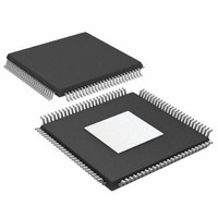
IC DAC 16BIT DUAL 1GSPS 100TQFP
Manufacturer
Analog Devices Inc
Datasheet
1.AD9776BSVZRL.pdf
(56 pages)
Specifications of AD9779BSVZ
Data Interface
Serial
Number Of Bits
16
Number Of Converters
2
Voltage Supply Source
Analog and Digital
Power Dissipation (max)
300mW
Operating Temperature
-40°C ~ 85°C
Mounting Type
Surface Mount
Package / Case
100-TQFP Exposed Pad, 100-eTQFP, 100-HTQFP, 100-VQFP
Resolution (bits)
16bit
Sampling Rate
1GSPS
Input Channel Type
Parallel
Digital Ic Case Style
QFP
No. Of Pins
160
Operating Temperature Range
-40°C To +85°C
Lead Free Status / RoHS Status
Lead free / RoHS Compliant
For Use With
AD9779A-EBZ - BOARD EVALUATION FOR AD9779A
Settling Time
-
Lead Free Status / RoHS Status
Lead free / RoHS Compliant, Lead free / RoHS Compliant
Available stocks
Company
Part Number
Manufacturer
Quantity
Price
Company:

Part Number:
AD9779BSVZ
Manufacturer:
AD
Quantity:
2 100
Company:
Part Number:
AD9779BSVZ
Manufacturer:
ADI
Quantity:
325
Company:
Part Number:
AD9779BSVZ
Manufacturer:
Analog Devices Inc
Quantity:
10 000
Part Number:
AD9779BSVZ
Manufacturer:
ADI/亚德诺
Quantity:
20 000
Company:
Part Number:
AD9779BSVZRL
Manufacturer:
Analog Devices Inc
Quantity:
10 000


In addition to this divisor function, DATACLK can be divided
by up to an additional factor of 4, according to the state of the
DATACLK divide register (Register 0x03, Bits<5:4>). For more
details, see Table 22).
Table 22. Extra DATACLK Divisor Ratio
Register 0x03, Bits<5:4>
00
01
10
11
The maximum divisor resulting from the combination of the
values in Table 21, and the DATACLK divide register is 32.
Manual Input Timing Correction
Correction of input timing can be achieved manually. The
correction function is controlled by Register 0x03, Bits<7:6>.
The function is programmed as shown in Table 23.
Table 23. Input Timing Correction Mode
Register 0x03, Bits<7:6>
00
01
10
11
Divider Ratio
1
2
4
1
Function
Error check disabled
Reserved
Reserved
Reserved
Rev. A | Page 45 of 56
Necessary corrections can be made by adjusting DATACLK
delay and the DATACLK invert bit (Register 2, Bit 2).
DATACLK delay can then be swept to find the range over which
the timing is valid. The final value for data delay should be the
value that corresponds to the middle of the valid timing range.
If a valid timing range is not found during this sweep, the user
should invert the DATACLK invert bit and repeat the process.
Multiple DAC Synchronization
The AD9779 has programmable features that allow the CMOS
digital data bus inputs and internal filters on multiple devices to
be synchronized. This means that the DATACLK output signal
on one AD9779 can be used to register the output data for a data
bus delivering data to multiple AD9779s. The details of this opera-
tion are given in the Analog Devices Application Note AN-822.
AD9776/AD9778/AD9779
Related parts for AD9779BSVZ
Image
Part Number
Description
Manufacturer
Datasheet
Request
R

Part Number:
Description:
BOARD EVALUATION FOR AD9779
Manufacturer:
Analog Devices Inc
Datasheet:
Part Number:
Description:
BOARD EVALUATION FOR AD9779
Manufacturer:
Analog Devices Inc
Datasheet:

Part Number:
Description:
±1.7g Dual-Axis IMEMS Accelerometer Evaluation Board
Manufacturer:
Analog Devices Inc
Datasheet:
Part Number:
Description:
Inertial Sensor Evaluation System
Manufacturer:
Analog Devices Inc
Datasheet:
Part Number:
Description:
Manufacturer:
Analog Devices Inc
Datasheet:
Part Number:
Description:
Manufacturer:
Analog Devices Inc
Datasheet:
Part Number:
Description:
Manufacturer:
Analog Devices Inc
Datasheet:
Part Number:
Description:
Manufacturer:
Analog Devices Inc
Datasheet:
Part Number:
Description:
Manufacturer:
Analog Devices Inc
Datasheet:
Part Number:
Description:
Manufacturer:
Analog Devices Inc
Datasheet:
Part Number:
Description:
Manufacturer:
Analog Devices Inc
Datasheet:
Part Number:
Description:
Manufacturer:
Analog Devices Inc
Datasheet:
Part Number:
Description:
Manufacturer:
Analog Devices Inc
Datasheet: