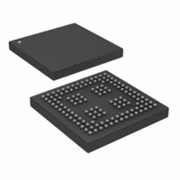
ADSP-21262SKBCZ200 Analog Devices Inc, ADSP-21262SKBCZ200 Datasheet - Page 39

ADSP-21262SKBCZ200
Manufacturer Part Number
ADSP-21262SKBCZ200
Description
IC DSP CTLR 32BIT 136CSPBGA
Manufacturer
Analog Devices Inc
Series
SHARC®r
Type
Fixed/Floating Pointr
Datasheet
1.ADSP-21262SKBCZ200.pdf
(48 pages)
Specifications of ADSP-21262SKBCZ200
Interface
DAI, SPI
Clock Rate
200MHz
Non-volatile Memory
ROM (512 kB)
On-chip Ram
256kB
Voltage - I/o
3.30V
Voltage - Core
1.20V
Operating Temperature
0°C ~ 70°C
Mounting Type
Surface Mount
Package / Case
136-CSPBGA
No. Of Bits
32 Bit
Frequency
200MHz
Supply Voltage
1.2V
Embedded Interface Type
SPI
No. Of I/o's
23
Supply Voltage Range
1.14V To 1.26V, 3.13V To 3.47V
Lead Free Status / RoHS Status
Lead free / RoHS Compliant
Other names
ADSP21262SKBCZ200
Available stocks
Company
Part Number
Manufacturer
Quantity
Price
Company:
Part Number:
ADSP-21262SKBCZ200
Manufacturer:
Analog Devices Inc
Quantity:
10 000
Part Number:
ADSP-21262SKBCZ200
Manufacturer:
ADI/亚德诺
Quantity:
20 000
ENVIRONMENTAL CONDITIONS
The ADSP-21262 processor is rated for performance under
T
Operating Conditions on Page
THERMAL CHARACTERISTICS
Table 32
JEDEC standards JESD51-2 and JESD51-6 and the junction-to-
board measurement complies with JESD51-8. Test board and
thermal via design comply with JEDEC standards JESD51-9
(mini-BGA) and JESD51-5 (integrated Heat Sink LQFP). The
junction-to-case measurement complies with MIL-STD-883.
All measurements use a 2S2P JEDEC test board.
Industrial applications using the mini-BGA package require
thermal vias, to an embedded ground plane, in the PCB. Refer to
JEDEC standard JESD51-9 for printed circuit board thermal
ball land and thermal via design information.
To determine the junction temperature of the device while on
the application PCB, use:
where:
T
T
package
Ψ
the typical value from
cates moving air).
P
applications and No. 216 for commercial)
AMB
J
CASE
D
JT
= junction temperature (°C)
= power dissipation (see EE Note No. 250 for industrial
= junction-to-top (of package) characterization parameter is
environmental conditions specified in the
= case temperature (°C) measured at the top center of the
Figure 33. Typical Output Delay or Hold vs. Load Capacitance
10
–4
–2
8
6
4
2
0
through
0
Y = 0.0488X – 1.5923
Table 36
T
J
(at Ambient Temperature)
=
50
Table 32
T
CASE
airflow measurements comply with
LOAD CAPACITANCE (pF)
15.
through
+
100
(
Ψ
JT
×
Table 36
P
D
)
150
Recommended
(Ψ
Rev. B | Page 39 of 48 | August 2005
JMT
indi-
200
Values of θ
design considerations (θ
used for a first-order approximation of T
where:
T
Values of θ
design considerations when an external heat sink is required.
Values of θ
design considerations. Note that the thermal characteristics val-
ues provided in
Table 32. Thermal Characteristics for Commercial
Grade 144-Lead LQFP
Table 33. Thermal Characteristics for Commercial
Grade 136-Ball BGA (no thermal vias in PCB)
Table 34. Thermal Characteristics for Commercial
Grade 136-Ball BGA (with thermal vias in PCB)
Parameter
θ
θ
θ
θ
Ψ
Ψ
Ψ
Parameter
θ
θ
θ
θ
Ψ
Ψ
Ψ
Parameter
θ
θ
θ
θ
Ψ
Ψ
Ψ
A
JA
JMA
JMA
JC
JA
JMA
JMA
JC
JA
JMA
JMA
JC
JT
JMT
JMT
JT
JMT
JMT
JT
JMT
JMT
= ambient temperature (°C)
JA
JC
JB
are provided for package comparison and PCB
are provided for package comparison and PCB
are provided for package comparison and PCB
Table 32
Airflow = 0 m/s
Airflow = 1 m/s
Airflow = 2 m/s
Airflow = 0 m/s
Airflow = 1 m/s
Airflow = 2 m/s
Condition
Airflow = 0 m/s
Airflow = 1 m/s
Airflow = 2 m/s
Airflow = 0 m/s
Airflow = 1 m/s
Airflow = 2 m/s
Condition
Airflow = 0 m/s
Airflow = 1 m/s
Airflow = 2 m/s
Airflow = 0 m/s
Airflow = 1 m/s
Airflow = 2 m/s
T
J
=
JMA
through
T
indicates moving air). θ
A
+
(
θ
Table 36
JA
×
P
D
J
by the equation:
Typical
32.5
28.9
27.8
7.8
0.5
0.8
1.0
Typical
31.0
27.3
26.0
6.99
0.16
0.30
0.35
Typical
27.7
24.1
23.0
6.85
0.14
0.26
0.31
)
ADSP-21262
are modeled values.
JA
can be
Unit
°C/W
°C/W
°C/W
°C/W
°C/W
°C/W
°C/W
Unit
°C/W
°C/W
°C/W
°C/W
°C/W
°C/W
°C/W
Unit
°C/W
°C/W
°C/W
°C/W
°C/W
°C/W
°C/W


