MOD5272-100IR NetBurner Inc, MOD5272-100IR Datasheet - Page 173
MOD5272-100IR
Manufacturer Part Number
MOD5272-100IR
Description
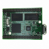
PROCESSOR MODULE FLASH MOD5272
Manufacturer
NetBurner Inc
Type
Controllers & Processorsr
Datasheets
1.MOD5272-100IR.pdf
(2 pages)
2.MOD5272-100IR.pdf
(3 pages)
3.MOD5272-100IR.pdf
(550 pages)
Specifications of MOD5272-100IR
Module/board Type
Processor Module
Ethernet Connection Type
10/100 Ethernet Port RJ-45
Operating Voltage
3.3 V
Product
Modules
Lead Free Status / RoHS Status
Lead free / RoHS Compliant
For Use With/related Products
MOD5272
For Use With
528-1001 - KIT DEVELOP NETWORK FOR MOD5272
Lead Free Status / Rohs Status
Lead free / RoHS Compliant
Other names
528-1008


MOTOROLA
15-11
Bits
7-6
21
20
19
18
17
16
10
9
8
5
TIMERPDN Timer power-down enable. Controls the clocking to the timer module.
UART1PDN UART1 power-down enable. Controls the clocking to the UART1 module. Clocking to the
UART0PDN UART0 power-down enable. Controls the clocking to the UART0 module. Clocking to the
UART1WK
UART0WK
GPIOPDN
QSPIPDN
USBPDN
USBWK
Field
MOS
—
—
QSPI power-down enable. Controls the clocking to the QSPI module.
0 Clock enabled.
1 Clock disabled.
0 Clock enabled.
1 Clock disabled.
Parallel port power-down enable. Controls the clocking to the parallel port module.
0 Clock enabled.
1 Clock disabled.
USB power-down enable. Controls the clocking to the USB module. Clocking to the USB
module may be turned on by USD_D+ or INT1/USB_WOR, at which time this bit is
automatically cleared.
0 Clock enabled.
1 Clock disabled.
UART1 module may be restored when a change in signal level is detected on UART1RxD, at
which time this bit is automatically cleared.
0 Clock enabled.
1 Clock disabled.
UART0 module may be restored when a change in signal level is detected on UART0RxD, at
which time this bit is automatically cleared.
0 Clock enabled.
1 Clock disabled.
Reserved, should be cleared.
USB wakeup enable. Allows clocking to the USB module to be restored when a change in
signal level is detected on USD_D+ or INT1/USB_WOR. See Table 6-6 for a description of the
interaction between the PDN and WK bits.
0 Wakeup disabled.
1 Wakeup enabled. USBPDN must also be set.
UART1 wakeup enable. Allows clocking to the UART1 module to be restored when a change in
signal level is detected on UART1RxD. See Table 6-6 for a description of the interaction
between the PDN and WK bits.
0 Wakeup disabled.
1 Wakeup enabled. UART1PDN must also be set.
UART0 wakeup enable. Allows clocking to the UART0 module to be restored when a change in
signal level is detected on UART0RxD. See Table 6-6 for a description of the interaction
between the PDN and WK bits.
0 Wakeup disabled.
1 Wakeup enabled. UART0PDN must also be set.
Reserved, should be cleared.
Main oscillator stop. Allows the MCF5272 to be put into stop mode, in which internal clocking is
stopped to the entire processor. To enter stop mode, the user must write to the ALPR and then
execute a STOP instruction. See Section 6.2.6, “Activate Low-Power Register (ALPR).” It is not
necessary to put any on-chip modules in power down mode. After setting this bit, a write
access must be made to the ALPR register to actually enter stop mode. D[31:0] are driven low,
and other bus signals are negated. Stop mode is exited when an interrupt is detected on one
the external interrupt pins, INT[6:1].
0 Stop mode disabled.
1 Stop mode enabled.
Table 6-5. PMR Field Descriptions (Continued)
Chapter 6. System Integration Module (SIM)
Description
Programming Model
6-9
Related parts for MOD5272-100IR
Image
Part Number
Description
Manufacturer
Datasheet
Request
R

Part Number:
Description:
Ethernet Modules & Development Tools MOD5272 Processor Board
Manufacturer:
NetBurner Inc
Datasheet:
Part Number:
Description:
Ethernet Modules & Development Tools MOD5272 Industrial Temperature
Manufacturer:
NetBurner Inc
Part Number:
Description:
Ethernet Modules & Development Tools MOD5272 MODULE
Manufacturer:
NetBurner Inc
Datasheet:

Part Number:
Description:
PROCESSOR MODULE FLASH
Manufacturer:
NetBurner Inc
Datasheet:

Part Number:
Description:
Ethernet Modules & Development Tools 32Bit 62MHz Core Module 50Pin DIP
Manufacturer:
NetBurner Inc
Datasheet:

Part Number:
Description:
BOARD SERIAL-ETHERNET 512K FLASH
Manufacturer:
NetBurner Inc
Datasheet:

Part Number:
Description:
PROCESSOR MODULE 512KB FLASH
Manufacturer:
NetBurner Inc
Datasheet:

Part Number:
Description:
DUAL PORT SERIAL-ETHERNET
Manufacturer:
NetBurner Inc
Datasheet:

Part Number:
Description:
PROCESSOR MODULE 512KB FLASH
Manufacturer:
NetBurner Inc
Datasheet:

Part Number:
Description:
MOD5234 10/100 ETHERNET MODULE
Manufacturer:
NetBurner Inc
Datasheet:

Part Number:
Description:
KIT DEVELOP NETWORK FOR MOD5282
Manufacturer:
NetBurner Inc
Datasheet:

Part Number:
Description:
KIT DEVELOP NETWORK FOR MOD5272
Manufacturer:
NetBurner Inc
Datasheet:

Part Number:
Description:
Ethernet ICs 32bit 147MHz CAN-to- Ethnt Device IndTemp
Manufacturer:
NetBurner Inc
Datasheet: