MOD5272-100IR NetBurner Inc, MOD5272-100IR Datasheet - Page 264
MOD5272-100IR
Manufacturer Part Number
MOD5272-100IR
Description
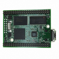
PROCESSOR MODULE FLASH MOD5272
Manufacturer
NetBurner Inc
Type
Controllers & Processorsr
Datasheets
1.MOD5272-100IR.pdf
(2 pages)
2.MOD5272-100IR.pdf
(3 pages)
3.MOD5272-100IR.pdf
(550 pages)
Specifications of MOD5272-100IR
Module/board Type
Processor Module
Ethernet Connection Type
10/100 Ethernet Port RJ-45
Operating Voltage
3.3 V
Product
Modules
Lead Free Status / RoHS Status
Lead free / RoHS Compliant
For Use With/related Products
MOD5272
For Use With
528-1001 - KIT DEVELOP NETWORK FOR MOD5272
Lead Free Status / Rohs Status
Lead free / RoHS Compliant
Other names
528-1008


Module Operation
12.2.1.1 USB Transceiver Interface
The USB module supports either an internal or external USB transceiver. USB_D+ and
USB_D- drive USB cable D+ and D- lines, respectively. With additional external protection
circuitry (see 12.5.3, “Recommended USB Protection Circuit”), equipment can be built that
complies with Universal Serial Bus Specification, Rev. 1.1. Transceiver performance
specifications are described in the Chapter 7 of the Universal Serial Bus Specification. See
note on page , [p. 12-1].
When the internal transceiver is selected, (USBEPCTL0[AFEEN] is cleared), the driven
outputs can be observed by using the parallel port A if these pins are configured for USB,
using the PACNT register, 17.2.1, “Port A Control Register (PACNT)”.
The USB module has separate power pins for the internal transceiver.
However, to reduce power consumption, USB_VDD may be left unconnected if either of
the following is true:
12.2.1.2 Clock Generator
The USB module requires two clock inputs; the system clock and a 48-MHz data clock. The
data clock source is selectable between the USB_ExtCLK pin or the system clock. The
clock generator automatically uses the external clock as the data clock if it detects the
presence of a clock signal on the USB_CLK pin during system reset. This automatic
selection can be overridden by setting bit USBEPCTL0[CLK_SEL], Section 12.3.2.13. If
a clock signal is not present on USB_CLK, the clock generator uses the system clock.
12.2.1.3 USB Control Logic
The control logic performs the following functions:
12-4
• The USB module is not used.
• An external transceiver is used.
• For transmitted data:
— Packet creation
— Parallel-to-serial conversion
— CRC generation
USB_GND should always be grounded.
In all cases, the system clock must be at least 24-MHz for the
USB module to function properly. If the system clock is used
for the USB data clock, the system clock frequency must be
48-MHz.
MCF5272 User’s Manual
NOTE:
NOTE:
MOTOROLA
Related parts for MOD5272-100IR
Image
Part Number
Description
Manufacturer
Datasheet
Request
R

Part Number:
Description:
Ethernet Modules & Development Tools MOD5272 Processor Board
Manufacturer:
NetBurner Inc
Datasheet:
Part Number:
Description:
Ethernet Modules & Development Tools MOD5272 Industrial Temperature
Manufacturer:
NetBurner Inc
Part Number:
Description:
Ethernet Modules & Development Tools MOD5272 MODULE
Manufacturer:
NetBurner Inc
Datasheet:

Part Number:
Description:
PROCESSOR MODULE FLASH
Manufacturer:
NetBurner Inc
Datasheet:

Part Number:
Description:
Ethernet Modules & Development Tools 32Bit 62MHz Core Module 50Pin DIP
Manufacturer:
NetBurner Inc
Datasheet:

Part Number:
Description:
BOARD SERIAL-ETHERNET 512K FLASH
Manufacturer:
NetBurner Inc
Datasheet:

Part Number:
Description:
PROCESSOR MODULE 512KB FLASH
Manufacturer:
NetBurner Inc
Datasheet:

Part Number:
Description:
DUAL PORT SERIAL-ETHERNET
Manufacturer:
NetBurner Inc
Datasheet:

Part Number:
Description:
PROCESSOR MODULE 512KB FLASH
Manufacturer:
NetBurner Inc
Datasheet:

Part Number:
Description:
MOD5234 10/100 ETHERNET MODULE
Manufacturer:
NetBurner Inc
Datasheet:

Part Number:
Description:
KIT DEVELOP NETWORK FOR MOD5282
Manufacturer:
NetBurner Inc
Datasheet:

Part Number:
Description:
KIT DEVELOP NETWORK FOR MOD5272
Manufacturer:
NetBurner Inc
Datasheet:

Part Number:
Description:
Ethernet ICs 32bit 147MHz CAN-to- Ethnt Device IndTemp
Manufacturer:
NetBurner Inc
Datasheet: