MOD5272-100IR NetBurner Inc, MOD5272-100IR Datasheet - Page 386
MOD5272-100IR
Manufacturer Part Number
MOD5272-100IR
Description
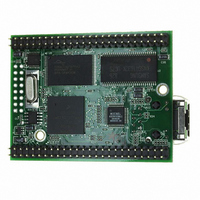
PROCESSOR MODULE FLASH MOD5272
Manufacturer
NetBurner Inc
Type
Controllers & Processorsr
Datasheets
1.MOD5272-100IR.pdf
(2 pages)
2.MOD5272-100IR.pdf
(3 pages)
3.MOD5272-100IR.pdf
(550 pages)
Specifications of MOD5272-100IR
Module/board Type
Processor Module
Ethernet Connection Type
10/100 Ethernet Port RJ-45
Operating Voltage
3.3 V
Product
Modules
Lead Free Status / RoHS Status
Lead free / RoHS Compliant
For Use With/related Products
MOD5272
For Use With
528-1001 - KIT DEVELOP NETWORK FOR MOD5272
Lead Free Status / Rohs Status
Lead free / RoHS Compliant
Other names
528-1008


Operation
If a break condition is detected (RxD is low for the entire character including the stop bit),
a character of all zeros is loaded into the receiver holding register (RHR) and
USRn[RB,RxRDY] are set. RxD must return to a high condition for at least one-half bit
time before a search for the next start bit begins.
The receiver detects the beginning of a break in the middle of a character if the break
persists through the next character time. If the break begins in the middle of a character, the
receiver places the damaged character in the Rx FIFO stack and sets the corresponding
USRn error bits and USRn[RxRDY]. Then, if the break lasts until the next character time,
the receiver places an all-zero character into the Rx FIFO and sets USRn[RB,RxRDY].
16.5.2.3 Transmitter FIFO
Whenever the CPU writes a character for transmission into UTB, the character is placed
into the 24-byte transmitter FIFO. UTB fills the last spot in the FIFO and holds the last
character to be transmitted. Visibility into the status of the FIFO is provided by various bits
and interrupts, as shown in Table 16-16.
16.5.2.4 Receiver FIFO
The FIFO stack is used in the UART’s receiver buffer logic. The FIFO is 24 bytes deep. The
receive buffer consists of the FIFO and a receiver shift register connected to the RxD (see
Figure 16-24). Data is assembled in the receiver shift register and loaded into the top empty
receiver holding register position of the FIFO. Similar to the transmitter, several status bits
and interrupts provide visibility into the status of the FIFO.
In addition to the data byte, three status bits, parity error (PE), framing error (FE), and
received break (RB), are appended to each data character in the FIFO; OE (overrun error)
is not appended. By programming the ERR bit in the channel’s mode register (UMR1n),
status is provided in character or block modes.
USRn[RxRDY] is set when at least one character is available to be read by the CPU. A read
of the receiver buffer produces an output of data from the top of the FIFO stack. After the
read cycle, the data at the top of the FIFO stack and its associated status bits are popped and
the receiver shift register can add new data at the bottom of the stack. The FIFO-full status
bit (FFULL) is set if all 24 stack positions are filled with data. Either the RxRDY or FFULL
bit can be selected to cause an interrupt.
16-26
USR[TxEMP] = 1 The transmitter FIFO and shift register are empty and a data underrun occurred.
USR[TxRDY] = 1
USR[FFULL] = 1
UTF[TXS]
UTF[TXB]
Status Bit
cleared, the FIFO is full and a subsequent write to the FIFO will be ignored.
At least one FIFO stage is available for a character to be transmitted. If this bit is
The programmed level of emptiness (UTF[TXS]) has been reached.
Indicates the level of emptiness of the transmitter FIFO
Indicates the number of characters, 0–24, in the transmitter FIFO
Table 16-16. Transmitter FIFO Status Bits
MCF5272 User’s Manual
Indicated Condition
MOTOROLA
Interrupt
Yes
Yes
Related parts for MOD5272-100IR
Image
Part Number
Description
Manufacturer
Datasheet
Request
R

Part Number:
Description:
Ethernet Modules & Development Tools MOD5272 Processor Board
Manufacturer:
NetBurner Inc
Datasheet:
Part Number:
Description:
Ethernet Modules & Development Tools MOD5272 Industrial Temperature
Manufacturer:
NetBurner Inc
Part Number:
Description:
Ethernet Modules & Development Tools MOD5272 MODULE
Manufacturer:
NetBurner Inc
Datasheet:

Part Number:
Description:
PROCESSOR MODULE FLASH
Manufacturer:
NetBurner Inc
Datasheet:

Part Number:
Description:
Ethernet Modules & Development Tools 32Bit 62MHz Core Module 50Pin DIP
Manufacturer:
NetBurner Inc
Datasheet:

Part Number:
Description:
BOARD SERIAL-ETHERNET 512K FLASH
Manufacturer:
NetBurner Inc
Datasheet:

Part Number:
Description:
PROCESSOR MODULE 512KB FLASH
Manufacturer:
NetBurner Inc
Datasheet:

Part Number:
Description:
DUAL PORT SERIAL-ETHERNET
Manufacturer:
NetBurner Inc
Datasheet:

Part Number:
Description:
PROCESSOR MODULE 512KB FLASH
Manufacturer:
NetBurner Inc
Datasheet:

Part Number:
Description:
MOD5234 10/100 ETHERNET MODULE
Manufacturer:
NetBurner Inc
Datasheet:

Part Number:
Description:
KIT DEVELOP NETWORK FOR MOD5282
Manufacturer:
NetBurner Inc
Datasheet:

Part Number:
Description:
KIT DEVELOP NETWORK FOR MOD5272
Manufacturer:
NetBurner Inc
Datasheet:

Part Number:
Description:
Ethernet ICs 32bit 147MHz CAN-to- Ethnt Device IndTemp
Manufacturer:
NetBurner Inc
Datasheet: