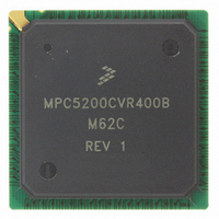
MPC5200CVR400B Freescale Semiconductor, MPC5200CVR400B Datasheet - Page 12

MPC5200CVR400B
Manufacturer Part Number
MPC5200CVR400B
Description
IC MPU 32BIT 400MHZ 272-PBGA
Manufacturer
Freescale Semiconductor
Specifications of MPC5200CVR400B
Processor Type
MPC52xx PowerPC 32-Bit
Speed
400MHz
Voltage
1.5V
Mounting Type
Surface Mount
Package / Case
272-PBGA
Processor Series
MPC52xx
Core
e300
Development Tools By Supplier
MEDIA5200KIT1E
Maximum Clock Frequency
400 MHz
Maximum Operating Temperature
+ 105 C
Mounting Style
SMD/SMT
I/o Voltage
2.5 V, 3.3 V
Minimum Operating Temperature
- 40 C
Core Size
32 Bit
No. Of I/o's
56
Ram Memory Size
16KB
Cpu Speed
400MHz
No. Of Timers
8
Embedded Interface Type
CAN, I2C, SCI, SPI
No. Of Pwm Channels
8
Digital Ic Case Style
TEPBGA
Rohs Compliant
Yes
Lead Free Status / RoHS Status
Lead free / RoHS Compliant
Features
-
Lead Free Status / Rohs Status
Lead free / RoHS Compliant
Available stocks
Company
Part Number
Manufacturer
Quantity
Price
Company:
Part Number:
MPC5200CVR400B
Manufacturer:
Marvell
Quantity:
1 001
Company:
Part Number:
MPC5200CVR400B
Manufacturer:
FREESCAL
Quantity:
200
Company:
Part Number:
MPC5200CVR400B
Manufacturer:
Freescale Semiconductor
Quantity:
10 000
Part Number:
MPC5200CVR400B
Manufacturer:
FREESCALE
Quantity:
20 000
Company:
Part Number:
MPC5200CVR400BM62C
Manufacturer:
FRRESCAL..
Quantity:
2 831
Electrical and Thermal Characteristics
Historically, the thermal resistance has frequently been expressed as the sum of a junction to case thermal
resistance and a case to ambient thermal resistance:
where:
R
change the case to ambient thermal resistance, R
the device, add a heat sink, change the mounting arrangement on printed circuit board, or change the
thermal dissipation on the printed circuit board surrounding the device. This description is most useful for
ceramic packages with heat sinks where some 90% of the heat flow is through the case to the heat sink to
ambient. For most packages, a better model is required.
A more accurate thermal model can be constructed from the junction to board thermal resistance and the
junction to case thermal resistance
used or where a substantial amount of heat is dissipated from the top of the package. The junction to board
thermal resistance describes the thermal performance when most of the heat is conducted to the printed
circuit board. This model can be used for either hand estimations or for a computational fluid dynamics
(CFD) thermal model.
To determine the junction temperature of the device in the application after prototypes are available, the
Thermal Characterization Parameter (Ψ
measurement of the temperature at the top center of the package case using the following equation:
where:
The thermal characterization parameter is measured per JESD51-2 specification using a 40-gauge type T
thermocouple epoxied to the top center of the package case. The thermocouple should be positioned, so
that the thermocouple junction rests on the package. A small amount of epoxy is placed over the
thermocouple junction and over approximately one mm of wire extending from the junction. The
thermocouple wire is placed flat against the package case to avoid measurement errors caused by cooling
effects of the thermocouple wire.
3.2
The MPC5200 System requires a system-level clock input SYS_XTAL. This clock input may be driven
directly from an external oscillator or with a crystal using the internal oscillator.
12
θJC
is device related and cannot be influenced by the user. The user controls the thermal environment to
Oscillator and PLL Electrical Characteristics
R
R
R
T
Ψ
P
T
D
θJA
θJC
θCA
JT
= thermocouple temperature on top of package (°C)
= power dissipation in package (W)
= thermal characterization parameter (°C/W)
= junction to ambient thermal resistance (°C/W)
= junction to case thermal resistance (°C/W)
= case to ambient thermal resistance (°C/W)
1-3
. The junction to case covers the situation where a heat sink will be
T
R
JT
MPC5200 Data Sheet, Rev. 4
J
θJA
) can be used to determine the junction temperature with a
= T
= R
T
+(Ψ
θCA
θJC
JT
. For instance, the user can change the air flow around
+R
× P
θCA
D
)
Freescale Semiconductor
Eqn. 2
Eqn. 3


