MC68EC020AA25 Freescale Semiconductor, MC68EC020AA25 Datasheet - Page 147
MC68EC020AA25
Manufacturer Part Number
MC68EC020AA25
Description
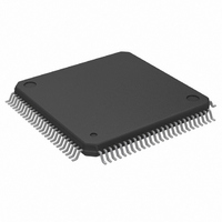
IC MPU 32BIT 25MHZ 100-QFP
Manufacturer
Freescale Semiconductor
Datasheet
1.MC68EC020AA16.pdf
(306 pages)
Specifications of MC68EC020AA25
Processor Type
M680x0 32-Bit
Speed
25MHz
Voltage
5V
Mounting Type
Surface Mount
Package / Case
100-QFP
Family Name
M68000
Device Core
ColdFire
Device Core Size
32b
Frequency (max)
25MHz
Instruction Set Architecture
RISC
Supply Voltage 1 (typ)
5V
Operating Supply Voltage (max)
5.25V
Operating Supply Voltage (min)
4.75V
Operating Temp Range
0C to 70C
Operating Temperature Classification
Commercial
Mounting
Surface Mount
Pin Count
100
Package Type
PQFP
Lead Free Status / RoHS Status
Lead free / RoHS Compliant
Features
-
Lead Free Status / Rohs Status
RoHS Compliant part
Electrostatic Device
Available stocks
Company
Part Number
Manufacturer
Quantity
Price
Company:

Part Number:
MC68EC020AA25
Manufacturer:
Freescale Semiconductor
Quantity:
10 000
Company:
Part Number:
MC68EC020AA25R
Manufacturer:
Freescale Semiconductor
Quantity:
10 000


causes the processor to enter the halted state. Refer to 6.2 Bus Fault Recovery for a
description of the processing that occurs after the frame is read into the internal registers.
If a format error or bus error exception occurs during the frame validation sequence of the
RTE instruction, either due to any of the errors previously described or due to an illegal
format code, the processor creates a normal four-word or a bus fault stack frame below
the frame that it was attempting to use. In this way, the faulty stack frame remains intact.
The exception handler can examine or repair the faulty frame. In a multiprocessor system,
the faulty frame can be left to be used by another processor of a different type (e.g., an
MC68010 or a future M68000 family processor) when appropriate.
6.2 BUS FAULT RECOVERY
An address error exception or a bus error exception indicates a bus fault. The saving of
the processor state for a bus error or address error is described in 6.1.2 Bus Error
Exception, and the restoring of the processor state by an RTE instruction is described in
6.1.12 Return from Exception.
Processor accesses of either data items or the instruction stream can result in bus errors.
When a bus error exception occurs while accessing a data item, the exception is taken
immediately after the bus cycle terminates. The processor may never access an
instruction that is part of the instruction stream. In this case, the bus error would not be
processed. For instruction faults, when the short bus fault stack frame applies, the
address of the pipe stage B word is the value in the PC plus four, and the address of the
stage C word is the value in the PC plus two. For the long format, the long word at SP +
$24 contains the address of the stage B word; the address of the stage C word is the
address of the stage B word minus two. Address error faults occur only for instruction
stream accesses, and the exceptions are taken before the bus cycles are attempted.
6.2.1 Special Status Word (SSW)
The internal SSW (see Figure 6-8) is one of several registers saved as part of the bus
fault exception stack frame. Both the short bus fault format and the long bus fault format
include this word at offset $A. The bus cycle fault stack frame formats are described in
detail in 6.4 Exception Stack Frame Formats.
The SSW information indicates whether the fault was caused by an access to the
instruction stream, data stream, or both. The high-order half of the SSW contains two
status bits each for the B and C stages of the instruction pipe. If an address error
exception occurs, the fault bits written to the stack frame are not set (they are only set due
to a bus error, as previously described), and the rerun bits alone show the cause of the
exception. Depending on the state of the pipeline, either RB and RC are set, or only RC is
set. To correct the pipeline contents and continue execution of the suspended instruction,
software must place the correct instruction stream data in the stage C and/or stage B
images requested by the rerun bits and must clear the rerun bits. The least significant half
of the SSW applies to data cycles only. Data and instruction stream faults may be pending
simultaneously; the fault handler should be able to recognize any combination of the FC,
FB, RC, RB, and DF bits.
6-22
M68020 USER’S MANUAL
MOTOROLA
Related parts for MC68EC020AA25
Image
Part Number
Description
Manufacturer
Datasheet
Request
R

Part Number:
Description:
Manufacturer:
Freescale Semiconductor, Inc
Datasheet:
Part Number:
Description:
Manufacturer:
Freescale Semiconductor, Inc
Datasheet:
Part Number:
Description:
Manufacturer:
Freescale Semiconductor, Inc
Datasheet:
Part Number:
Description:
Manufacturer:
Freescale Semiconductor, Inc
Datasheet:
Part Number:
Description:
Manufacturer:
Freescale Semiconductor, Inc
Datasheet:
Part Number:
Description:
Manufacturer:
Freescale Semiconductor, Inc
Datasheet:
Part Number:
Description:
Manufacturer:
Freescale Semiconductor, Inc
Datasheet:
Part Number:
Description:
Manufacturer:
Freescale Semiconductor, Inc
Datasheet:
Part Number:
Description:
Manufacturer:
Freescale Semiconductor, Inc
Datasheet:
Part Number:
Description:
Manufacturer:
Freescale Semiconductor, Inc
Datasheet:
Part Number:
Description:
Manufacturer:
Freescale Semiconductor, Inc
Datasheet:
Part Number:
Description:
Manufacturer:
Freescale Semiconductor, Inc
Datasheet:
Part Number:
Description:
Manufacturer:
Freescale Semiconductor, Inc
Datasheet:
Part Number:
Description:
Manufacturer:
Freescale Semiconductor, Inc
Datasheet:
Part Number:
Description:
Manufacturer:
Freescale Semiconductor, Inc
Datasheet: