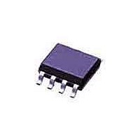
KMZ41 /T3 NXP Semiconductors, KMZ41 /T3 Datasheet - Page 4

KMZ41 /T3
Manufacturer Part Number
KMZ41 /T3
Description
Board Mount Hall Effect / Magnetic Sensors SNSR MAGNETC TAPE-13
Manufacturer
NXP Semiconductors
Datasheet
1.KMZ41_T3.pdf
(10 pages)
Specifications of KMZ41 /T3
Package / Case
SO
Mounting Style
SMD/SMT
Maximum Operating Temperature
+ 150 C
Minimum Operating Temperature
- 40 C
Supply Voltage (min)
5 V
Supply Voltage (max)
9 V
Lead Free Status / Rohs Status
Lead free / RoHS Compliant
Other names
KMZ41,118
NXP Semiconductors
7. Characteristics
Table 6.
T
[1]
[2]
[3]
[4]
[5]
[6]
[7]
[8]
[9]
KMZ41
Product data sheet
Symbol
V
V
TCV
R
TCR
V
TCV
FH
k
TCk
Δα
amb
CC
peak
offset
bridge
Applicable for bridge 1 and bridge 2.
Bridge resistance between pin 4 and pin 8, pin 3 and pin 7, pin 5 and pin 1, pin 6 and pin 2.
Δα = |α
from the third and fifth harmonics of the spectrum of V
TCV
TCR
TCV
FH
FH
TCk
peak
offset
bridge
k
= 25
=
1
2
peak
bridge
offset
100
=
=
=
°
real
C and H
Characteristics
100
100
100
×
=
− α
=
Parameter
supply voltage
peak voltage
temperature coefficient of peak
voltage
bridge resistance
temperature coefficient of
bridge resistance
offset voltage
temperature coefficient of
offset voltage
hysteresis of output voltage
amplitude synchronism
temperature coefficient of
amplitude synchronism
angular inaccuracy
V
--------------- -
V
=
×
×
×
100
peak1
peak2
meas
V
------------------------------------------------------------------------------------------------- -
100
--------------------------------------------------------------------------------------- -
k at 25 °C
offset
V
---------------------------------------------------------------------------------------------------------------------------
V
---------------------------------------------------------------------------------------------------------------
(
ext
O1
O2
×
|; V
k at 150 °C
×
(
-------------------------------------------------------------------------------------------------- -
V
= 100 kA/m, V
(
(
V
(
67.5°
22.5°
offset
peak
------------------------------------------------------------------------------------------------------ -
R
R
at 150 °C
peak
bridge
bridge
150 °C
(
= 0 V; inaccuracy of angular measurement due to deviation from ideal sinusoidal characteristics, calculated
(
at 25 °C
)
)135°
)90°
at 150 °C
×
(
(
at 25 °C
at 150 °C
(
150 °C
) k at 40
→ ° V
) V
–
–
→
2 V
–
(
0
CC
×
–
(
)
2 V
45
40
×
offset
×
) V
–
= 5 V unless otherwise specified.
° V
peak2
)
–
(
–
–
150 °C
°C
) R
×
–
(
peak1
O2
All information provided in this document is subject to legal disclaimers.
–
–
(
(
peak
40
at 40
)
150 °C
O1
(
°C
22.5°
bridge
–
°C
(
(
)
67.5°
see
Conditions
see
T
T
per supply voltage;
see
per supply voltage;
T
see
T
at 40
–
Rev. 6 — 18 November 2010
amb
amb
amb
amb
)
(
)
°C
–
–
)0°
(
–
at 40
40
O
Figure 2
Figure 2
Figure 2
Figure 3
(
)45°
= −40 °C to +150 °C
= −40 °C to +150 °C
= −40 °C to +150 °C;
= −40 °C to +150 °C
.
)
–
→
–
°C
°C
40
90
)
)
→
°C
)
°C
°
135
)
)
)
°
[1][2]
[1][3]
[1][4]
[1][5]
[1][6]
[1]
[1]
[1]
[7]
[8]
[9]
Min
-
73
−0.38
2.0
0.31
−2
−2
0
99
−0.005
0
2.5
Typ
5
81
−0.41
0.33
-
-
0.01
100
0
0.1
Magnetic field sensor
Max
9
89
−0.44
3.0
0.35
+2
+2
0.04
101
+0.005
0.25
© NXP B.V. 2010. All rights reserved.
KMZ41
Unit
V
mV
%/K
kΩ
%/K
mV/V
(μV/V)/K
%FS
%
deg
%/K
4 of 10


