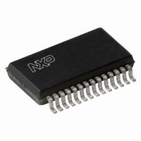
UDA1341TS/N1,512 NXP Semiconductors, UDA1341TS/N1,512 Datasheet - Page 17

UDA1341TS/N1,512
Manufacturer Part Number
UDA1341TS/N1,512
Description
IC AUDIO CODEC MINIDISC 28-SSOP
Manufacturer
NXP Semiconductors
Type
Stereo Audior
Datasheet
1.UDA1341TSN1512.pdf
(34 pages)
Specifications of UDA1341TS/N1,512
Package / Case
28-SSOP (0.200", 5.30mm Width)
Data Interface
Serial
Resolution (bits)
20 b
Number Of Adcs / Dacs
4 / 2
Sigma Delta
Yes
S/n Ratio, Adcs / Dacs (db) Typ
97 / 100
Voltage - Supply, Analog
2.4 V ~ 3.6 V
Voltage - Supply, Digital
2.4 V ~ 3.6 V
Operating Temperature
-20°C ~ 85°C
Mounting Type
Surface Mount
Number Of Adc Inputs
4
Number Of Dac Outputs
2
Conversion Rate
48 KSPs
Interface Type
Serial (I2S), L3
Resolution
20 bit
Operating Supply Voltage
2.4 V to 3.6 V
Maximum Operating Temperature
+ 85 C
Mounting Style
SMD/SMT
Minimum Operating Temperature
- 20 C
Number Of Channels
4 ADC, 2 DAC
Supply Current
12.5 mA
Lead Free Status / RoHS Status
Lead free / RoHS Compliant
Other names
568-1154-5
935254530512
UDA1341TSDB
935254530512
UDA1341TSDB
NXP Semiconductors
7.21.2
Table 17 Data transfer of type ‘DATA0’
7.21.2.1
A 6-bit value to program the left and right channel volume
attenuation. The range is from 0 to −∞ dB in steps of 1 dB.
The default setting is given in Table 5.
Table 18 Volume settings
2002 May 16
BIT 7 BIT 6 BIT 5 BIT 4 BIT 3 BIT 2 BIT 1 BIT 0
VC5
Economy audio CODEC for MiniDisc (MD)
home stereo and portable applications
0
0
1
1
1
0
0
0
0
1
1
1
1
1
:
VC4
DATA0
0
1
0
1
1
0
0
0
0
1
1
1
1
1
:
Volume control
VC5
VC3
BB3
DIRECT CONTROL
PP
0
1
0
0
0
0
1
1
1
1
1
:
VC4
BB2
DE1
ED4
VC2
0
0
0
0
0
0
1
1
1
1
:
VC3
BB1
DE0
ED3
VC1
0
0
0
1
1
1
0
0
1
1
:
VC2
ED2
VC0
BB0
EA2
MT
0
1
0
1
1
0
1
0
1
:
VC1
TR1
EA1
ED1
VOLUME
M1
(dB)
−58
−59
−60
−∞
−∞
−1
−2
0
0
:
VC0 VC = volume control (6 bits)
TR0
EA0
ED0 ED = extended data (5 bits)
M0
17
BB = bass boost (4 bits)
TR = treble (2 bits)
PP = peak detection position
DE = de-emphasis (2 bits)
MT = mute
M = mode switch (2 bits)
EA = extended address (3 bits)
7.21.2.2
A 4-bit value to program the bass boost settings. The used
set depends on the mode bits. The default setting is given
in Table 5.
Table 19 Bass boost settings
BB3 BB2 BB1 BB0
0
0
0
0
0
0
0
0
1
1
1
1
1
1
1
0
0
0
0
1
1
1
1
0
0
0
0
1
1
1
Bass boost
REGISTER SELECTED
0
0
1
1
0
0
1
1
0
0
1
1
0
0
1
0
1
0
1
0
1
0
1
0
1
0
1
0
1
0
FLAT
(dB)
0
0
0
0
0
0
0
0
0
0
0
0
0
0
0
BASS BOOST
UDA1341TS
Product specification
MIN.
(dB)
10
12
14
16
18
18
18
18
18
18
0
2
4
6
8
MAX.
(dB)
10
12
14
16
18
20
22
24
24
24
0
2
4
6
8


