LM4550BVH/NOPB National Semiconductor, LM4550BVH/NOPB Datasheet - Page 27
LM4550BVH/NOPB
Manufacturer Part Number
LM4550BVH/NOPB
Description
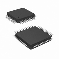
IC AC '97 AUDIO CODEC 48-LQFP
Manufacturer
National Semiconductor
Type
Audio Codec '97r
Specifications of LM4550BVH/NOPB
Data Interface
Serial
Resolution (bits)
18 b
Number Of Adcs / Dacs
2 / 2
Sigma Delta
Yes
Dynamic Range, Adcs / Dacs (db) Typ
90 / 89
Voltage - Supply, Analog
4.2 V ~ 5.5 V
Voltage - Supply, Digital
3 V ~ 5.5 V
Operating Temperature
-40°C ~ 85°C
Mounting Type
Surface Mount
Package / Case
48-LQFP
Audio Codec Type
Stereo
No. Of Adcs
2
No. Of Dacs
2
No. Of Input Channels
8
No. Of Output Channels
3
Adc / Dac Resolution
18bit
Sampling Rate
48kSPS
Interface Type
Serial
Supply Voltage Range
3V To 5.5V, 4.2V
Rohs Compliant
Yes
Lead Free Status / RoHS Status
Lead free / RoHS Compliant
Other names
*LM4550BVH
*LM4550BVH/NOPB
LM4550BVH
*LM4550BVH/NOPB
LM4550BVH
Available stocks
Company
Part Number
Manufacturer
Quantity
Price
Company:

Part Number:
LM4550BVH/NOPB
Manufacturer:
STM
Quantity:
1 872
Company:
Part Number:
LM4550BVH/NOPB
Manufacturer:
Texas Instruments
Quantity:
10 000


Improving System Performance
The audio codec is capable of dynamic range performance
in excess of 90 dB., but the user must pay careful attention
to several factors to achieve this. A primary consideration is
keeping analog and digital grounds separate, and connect-
ing them together in only one place. Some designers show
the connection as a zero ohm resistor, which allows naming
the nets separately. Although it is possible to use a two layer
board, it is recommended that a minimum of four layers be
used, with the two inside layers being analog ground and
digital ground. If EMI is a system consideration, then as
many as eight layers have been successfully used. The 12
and 25 MHz. clocks can have significant harmonic content
depending on the rise and fall times. Bypass capacitors
should be very close to the package. The analog VDD pins
should be supplied from a separate regulator to reduce
noise. By operating the digital portion on 3.3 V. instead of 5
V. an additional 0.5-0.7 dB improvement can be obtained.
The bandgap reference and the anti-pop slow turn-on circuit
were improved in the LM4550B. A pullup resistor is not
required on V
kohm resistor can be left on the pc board, but the tempera-
ture coefficient will improve with no resistor on this pin. In
addition, the THD will improve by 0.2–0.5 dB. The external
capacitor is charged by an internal current source, ramping
the voltage slowly. This results in slow turn-on of the audio
stages, eliminating “pops and clicks”. Thus, turn-on perfor-
mance is also improved. The pullup resistor, in conjunction
with the internal impedance and the external capacitor, form
a frequency dependent divider from the analog supply. Noise
on the analog supply will be coupled into the audio path, with
approximately 30 dB. of attenuation. Although this is not a
large amount if the noise on the supply is tens of millivolts, it
will prevent SNR from exceeding 80 dB.
In Figure 1 and Figure 2, the input coupling capacitors are
shown as 1 µF capacitors. This is only necessary for extend-
ing the response down to 20 Hz. for music applications. For
telematics or voice applications, the lower 3 dB. point can be
much higher. Using a guaranteed input resistance of 10 kΩ,
(40 kΩ typical), a 0.1 µF capacitor may be used. The lower 3
dB point will still be below 300 Hz. By using a smaller
capacitor, the package size may be reduced, leading to a
lower system cost.
Backwards Compatibility
The LM4550B is improved compared with the LM4550. If it is
required to build a board that will use either part, a 10 kΩ
resistor must be added from the V
the LM4550. It is not required for the LM4550B. Addition of
this resistor will slightly increase the temperature coefficient
of the internal bandgap reference and slightly decrease the
THD performance, but overall performance will still be better
than the LM4550.
The LM4550 requires that pins 1 and 9 (DV
directly to a 27 nH. inductor before going to the 3.3 Volt
digital supply and the bypass capacitors. The inductor is not
required for the LM4550B and should not be used.
Multiple Codecs
EXTENDED AC LINK
Up to four codecs can be supported on the extended AC
Link. These multiple codec implementations should run off a
common BIT_CLK generated by the Primary Codec. All
REF
, pin 27. For an existing design, the 10
REF
pin (pin 27) to AV
DD
) connect
DD
for
27
codecs share the AC ’97 Digital Controller output signals,
SYNC, SDATA_OUT, and RESET#. Each codec, however,
supplies its own SDATA_IN signal back to the controller, with
the result that the controller requires one dedicated input pin
per codec (Figure 9).
By definition there can be one Primary Codec and up to
three Secondary Codecs on an extended AC Link. The
Primary Codec has a Codec Identity = (ID1, ID0) = ID = 00
while Secondary Codecs take identities equal to 01, 10 or 11
(see Table 1). The Codec Identity is also used as a chip
select function. This allows the Command and Status regis-
ters in any of the codecs to be individually addressed al-
though the access mechanism for Secondary Codecs differs
slightly from that for a Primary.
The Identity control pins, ID1#, ID0# (pins 46 and 45) are
internally pulled up to DV
configured as ’Primary’ either by leaving ID1#, ID0# open
(NC) or by strapping them externally to DV
The difference between Primary and Secondary codec
modes is in their timing source; in the AMAP Slot-to-DAC
mapping used in Output Frames carried by SDATA_OUT;
and in the Tag Bit handling in Output Frames for Command/
Status register access. For a timing source, a Primary codec
divides down by 2 the frequency of the signal on XTAL_IN
and also generates this as the BIT_CLK output for the use of
the controller and any Secondary codecs. Secondary co-
decs use BIT_CLK as an input and as their timing source
and do not use XTAL_IN or XTAL_OUT, The AMAP map-
pings are given in Table 1 and the use of Tag Bits is de-
scribed below.
SECONDARY CODEC REGISTER ACCESS
For Secondary Codec access, the controller must set the tag
bits for Command Address and Data in the Output Frame as
invalid (i.e. equal to 0). The Command Address and Data tag
bits are in slot 0, bits 14 and 13 and Output Frames are
those in the SDATA_OUT signal from controller to codec.
The controller must also place the non-zero value (01, 10, or
11) corresponding to the Identity (ID1, ID0) of the target
Secondary Codec into the Codec ID field (slot 0, bits 1 and 0)
in that same Output Frame. The value set in the Codec ID
field determines which of the three possible Secondary Co-
decs is accessed. Unlike a Primary Codec, a Secondary
Codec will disregard the Command Address and Data tag
bits when there is a match between the 2-bit Codec ID value
(slot 0, bits 1 and 0) and the Codec Identity (ID1, ID0).
Instead it uses the Codec-ID/Identity match to indicate that
the Command Address in slot 1 and (if a “write”) the Com-
mand Data in slot 2 are valid.
When reading from a Secondary Codec, the controller must
send the correct Codec ID bits (i.e. the target Codec Identity
in slot 0, bits 1 and 0) along with the read-request bit (slot 1,
bit 19) and target register address (slot 1, bits 18 – 12). To
write to a Secondary Codec, a controller must send the
correct Codec ID bits when slot 1 contains a valid target
register address and “write” indicator bit and slot 2 contains
valid target register data. A write operation is only valid if the
register address and data are both valid and sent within the
same frame. When accessing the Primary Codec, the Codec
ID bits are cleared and the tag bits 14 and 13 resume their
role indicating the validity of Command Address and Data in
slots 1 and 2.
The use of the tag bits in Input Frames (carried by the
SDATA_IN signal) is the same for Primary and Secondary
Codecs.
DD
. The Codec may therefore be
DD
(digital supply).
www.national.com
Related parts for LM4550BVH/NOPB
Image
Part Number
Description
Manufacturer
Datasheet
Request
R

Part Number:
Description:
IC,Soundcard Circuits,QFP,48PIN,PLASTIC
Manufacturer:
National Semiconductor

Part Number:
Description:
Ac ?97 Rev 2.1 Multi-channel Audio Codec With Stereo Headphone Amplifier, Sample Rate Conversion And National 3d Sound
Manufacturer:
National Semiconductor Corporation
Datasheet:
Part Number:
Description:
National Semiconductor [8-Bit D/A Converter]
Manufacturer:
National Semiconductor
Datasheet:
Part Number:
Description:
National Semiconductor [Media Coprocessor]
Manufacturer:
National Semiconductor
Datasheet:
Part Number:
Description:
Digitally Controlled Tone and Volume Circuit with Stereo Audio Power Amplifier, Microphone Preamp Stage and National 3D Sound
Manufacturer:
National Semiconductor
Datasheet:
Part Number:
Description:
Digitally Controlled Tone and Volume Circuit with Stereo Audio Power Amplifier, Microphone Preamp Stage and National 3D Sound
Manufacturer:
National Semiconductor
Datasheet:
Part Number:
Description:
AC97 Rev 2 Codec with Sample Rate Conversion and National 3D Sound
Manufacturer:
National Semiconductor
Part Number:
Description:
Manufacturer:
National Semiconductor
Datasheet:
Part Number:
Description:
Manufacturer:
National Semiconductor
Datasheet:
Part Number:
Description:
General Purpose, Low Voltage, Low Power, Rail-to-Rail Output Operational Amplifiers
Manufacturer:
National Semiconductor
Datasheet:
Part Number:
Description:
8-bit 20 MSPS flash A/D converter.
Manufacturer:
National Semiconductor
Datasheet:
Part Number:
Description:
Low Noise Quad Operational Amplifier
Manufacturer:
National Semiconductor
Datasheet:
Part Number:
Description:
Quad Differential Line Receivers
Manufacturer:
National Semiconductor
Datasheet:
Part Number:
Description:
Quad High Speed Trapezoidal? Bus Transceiver
Manufacturer:
National Semiconductor
Datasheet: