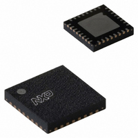
UDA1380HN/N2,118 NXP Semiconductors, UDA1380HN/N2,118 Datasheet - Page 28

UDA1380HN/N2,118
Manufacturer Part Number
UDA1380HN/N2,118
Description
IC AUDIO CODEC MINIDISC 32HVQFN
Manufacturer
NXP Semiconductors
Type
Stereo Audior
Datasheet
1.UDA1380HNN2118.pdf
(68 pages)
Specifications of UDA1380HN/N2,118
Package / Case
32-VFQFN Exposed Pad
Data Interface
I²C, Serial
Resolution (bits)
24 b
Number Of Adcs / Dacs
2 / 2
Sigma Delta
No
S/n Ratio, Adcs / Dacs (db) Typ
97 / 100
Voltage - Supply, Analog
2.4 V ~ 3.6 V
Voltage - Supply, Digital
2.4 V ~ 3.6 V
Operating Temperature
-40°C ~ 85°C
Mounting Type
Surface Mount
Interface Type
Serial (I2C)
Resolution
24 bit
Operating Supply Voltage
3 V
Maximum Operating Temperature
+ 85 C
Mounting Style
SMD/SMT
Minimum Operating Temperature
- 40 C
Supply Current
10 mA
Thd Plus Noise
- 85 dB
Lead Free Status / RoHS Status
Lead free / RoHS Compliant
Lead Free Status / RoHS Status
Lead free / RoHS Compliant, Lead free / RoHS Compliant
Other names
935271001118
UDA1380HN-T
UDA1380HN-T
UDA1380HN-T
UDA1380HN-T
10.3
Table 14 shows the I
The format of the READ cycle is as follows:
1. The microcontroller begins by asserting a start condition (S).
2. The first byte (8 bits) contains the device address ‘00110A
3. The UDA1380 asserts an acknowledge (A).
4. The microcontroller writes the 8-bit address (ADDR) of the UDA1380 register from which the data will be read.
5. The UDA1380 acknowledges this register address (A).
6. The microcontroller generates a repeated start (Sr).
7. The microcontroller generates the device address ‘00110A
8. The UDA1380 asserts an acknowledge (A).
9. The UDA1380 sends two bytes of data with the Most Significant (MS) byte first, followed by the Least Significant (LS) byte; after each byte the
10. After each pair of bytes transmitted, the register address is auto-incremented; after each byte the microcontroller asserts an acknowledge (A).
11. The microcontroller stops this cycle by generating a negative acknowledge (NA).
12. The UDA1380 frees the I2C-bus allowing the microcontroller to generate a stop condition (P).
Table 14 Master transmitter reads from the UDA1380 registers in the I
S
microcontroller asserts an acknowledge (A).
INITIAL BYTE
ADDRESS
READ cycle
00110A
DEVICE
1
0
2
R/W
C-bus configuration for a READ cycle. The READ cycle is used to read the data values from the internal registers.
0
A
ADDR
ACKNOWLEDGE FROM UDA1380
A
Sr
REGISTER
ADDRESS
00110A
1
0
1
1
0’ and the R/W bit is set to logic 0 (WRITE).
0’ again, but this time the R/W bit is set to logic 1 (READ).
R/W
1
2
C-bus mode
A
MS data
byte
auto increment if repeated n groups of 2 bytes are transmitted
MS1
ACKNOWLEDGE FROM MICROCONTROLLER
A
LS data
byte
LS1
A ... A ... A
MSn
A
LSn
NA
P


