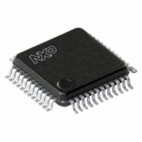
UCB1400BE,151 NXP Semiconductors, UCB1400BE,151 Datasheet - Page 17

UCB1400BE,151
Manufacturer Part Number
UCB1400BE,151
Description
IC AUDIO CODEC 3.3V 48-LQFP
Manufacturer
NXP Semiconductors
Type
Audio Codec '97r
Datasheet
1.UCB1400BEFE.pdf
(63 pages)
Specifications of UCB1400BE,151
Package / Case
48-LQFP
Data Interface
Serial
Resolution (bits)
20 b
Number Of Adcs / Dacs
2 / 2
Sigma Delta
No
S/n Ratio, Adcs / Dacs (db) Typ
97 / 91
Voltage - Supply, Analog
3 V ~ 3.6 V
Voltage - Supply, Digital
3 V ~ 3.6 V
Operating Temperature
-40°C ~ 85°C
Mounting Type
Surface Mount
Mounting Style
SMD/SMT
Lead Free Status / RoHS Status
Lead free / RoHS Compliant
Other names
935269304151
UCB1400BE-SNXP
UCB1400BE-SNXP
UCB1400BE-SNXP
UCB1400BE-SNXP
Available stocks
Company
Part Number
Manufacturer
Quantity
Price
Company:
Part Number:
UCB1400BE,151
Manufacturer:
NXP Semiconductors
Quantity:
10 000
Philips Semiconductors
9397 750 09611
Product data
Fig 11. AC Link power-down/power-up sequence.
SDATA_OUT
SDATA_IN
BIT_CLK
IRQOUT
SYNC
prev. frame
prev. frame
slot 12
slot 12
8.7.1 ATE in-circuit test mode
8.7.2 Vendor-specific test mode
8.7 Test modes
TAG
TAG
POWER-DOWN FRAME
Before enabling wake-up via IRQOUT or GIEN bit, the UCB1400 must be enabled for
interrupt by setting the appropriate bits in the Positive INT Enable register (0x5E) and
Negative INT Enable register (0x60). The INT Clear/Status register (0x62) should
then be cleared of any previous interrupts before going to low-power mode.
AC ’97 Component Specification defines two test modes. One is for ATE in-circuit
test, and the other if for vendor-specific tests. The UCB1400 enters the ATE in-circuit
test mode if SDATA_OUT is sampled HIGH at the trailing edge of RESET. The
UCB1400 enters the vendor-specific test mode when coming out of reset if SYNC is
HIGH. These cases will never occur during standard operating conditions.
Regardless of the test mode, the AC ’97 Controller must issue a cold reset to resume
normal operation of the UCB1400.
When the UCB1400 is placed in the ATE test mode, its digital AC-link outputs (i.e.,
BIT_CLK and SDATA_IN) shall be driven to a high impedance state. This allows ATE
in-circuit testing of the AC ’97 Controller.
When the UCB1400 is placed in the vendor-specific test mode, the Test Control
register (Index 0x6E) determines the kind of tests to be performed.
Refer to
Write to
0x26
Data
PR4
Section 12 “Register definition”
SLEEP STATE
Rev. 02 — 21 June 2002
for details.
WAKE EVENT
Audio codec with touch screen controller
and power management monitor
© Koninklijke Philips Electronics N.V. 2002. All rights reserved.
TAG
TAG
UCB1400
NEW AUDIO FRAME
Slot 1
Slot 1
Slot 2
Slot 2
SN00251
17 of 63


