PKJ4113EPI Ericsson Power Modules, PKJ4113EPI Datasheet - Page 14
PKJ4113EPI
Manufacturer Part Number
PKJ4113EPI
Description
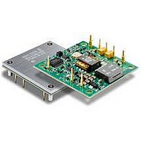
DC/DC Converters & Regulators 12 Vdc 8.3A Iso Input 48V 100W
Manufacturer
Ericsson Power Modules
Series
PKJ-Er
Datasheet
1.PKJ4618GEPI.pdf
(31 pages)
Specifications of PKJ4113EPI
Product
Isolated
Output Power
100 W
Input Voltage Range
36 V to 75 V
Number Of Outputs
1
Output Voltage (channel 1)
12 V
Output Current (channel 1)
8.3 A
Isolation Voltage
1.5 KV
Package / Case Size
Half Brick
Output Type
Isolated
Lead Free Status / Rohs Status
Lead free / RoHS Compliant
Available stocks
Company
Part Number
Manufacturer
Quantity
Price

Part Number:
PKJ4113EPI
Manufacturer:
ERICSSON/爱立信
Quantity:
20 000
Part Number:
PKJ4113EPIHS
Manufacturer:
ERICSSON/爱立信
Quantity:
20 000


E
3.3V, 30A / 100W Electrical Specification
T
Typical values given at: T
Characteristics
V
V
V
C
P
SVR
η
P
P
P
f
V
V
V
t
t
t
t
t
I
I
I
C
V
OVP
Note 1: No extra output filter used
Prepared (also subject responsible if other)
EJUNBLI
Approved
SEC/D (Betty Wu))
PKJ 4000E series Direct Converters
Input 36-75 V, Output up to 30 A / 100 W
s
tr
r
s
f
RC
O
lim
sc
P1
I
Ioff
Ion
O
d
li
RC
Oi
O
tr
Oac
I
out
= -40 to +90ºC, V
Input voltage range
Turn-off input voltage
Turn-on input voltage
Internal input capacitance
Output power
Supply voltage rejection (ac)
Efficiency
Power Dissipation
Input idling power
Input standby power
Switching frequency
Output voltage initial setting and
accuracy
Output adjust range
Output voltage tolerance band
Idling voltage
Line regulation
Load regulation
Load transient
voltage deviation
Load transient recovery time
Ramp-up time
(from 10−90 % of V
Start-up time
(from V
Vin shutdown fall time
(from V
RC start-up time
RC shutdown fall time
(from RC off to 10% of V
Output current
Current limit threshold
Short circuit current
Recommended Capacitive Load
Output ripple & noise
Over voltage protection
I
I
off to 10% of V
connection to 90% of V
I
= 36 to 75 V, sense pins connected to output pins unless otherwise specified under Conditions.
P1
Oi
)
= +25°C, V
O
)
O
)
Oi
)
I
= 53 V, max I
f = 100 Hz sinewave, 1 Vp-p
max I
I
V
max I
V
0-100% of max I
I
max I
V
max I
T
T
T
Conditions
Decreasing input voltage
Increasing input voltage
Output voltage initial setting
50 % of max I
max I
50 % of max I
max I
T
V
max I
see Note 1
10-100% of max I
max I
I
max I
I
See ripple & noise section,
max I
T
max I
O
O
O
O
P1
P1
P1
P1
P1
I
I
I
I
= 0 A, V
= 0 A
= 53 V, Load step 25-75-25 % of
= 0 A
= 0 A
= 53 V (turned off with RC)
= 53 V, See operating information
= 53 V, 0 - 100% of max I
= +25°C, V
< max T
= 25ºC, V
= 25ºC
= +25°C, V
O
O
O
O
O
O
O
O
O
O
O
, di/dt = 5 A/
, V
, V
O
Oi
I
Checked
ESHUHAN
I
, unless otherwise specified under Conditions.
= 48 V
= 53 V
P1
O
O
O
I
I
< 0.5 V
, V
= 53 V, 10-100% of
= 53 V, I
O
O
I
µ
= 48 V
s,
O
= 30 A
O
Ericsson Internal
PRODUCT SPECIFICATION
No.
2/1301- BMR 623 Uen
Date
2009-09-07
86.5
3.23
2.64
3.20
3.23
125
min
3.9
36
0
0
0
Technical Specification
EN/LZT 146 383 R3A September 2009
© Ericsson AB
Rev
C
±500
88.5
88.5
12.5
0.25
3.30
140
N/A
N/A
N/A
N/A
N/A
120
typ
6.4
32
34
70
92
92
50
15
20
35
40
2
Reference
13.7
3.37
3.63
3.40
3.37
TBD
max
100
155
180
6.0
75
30
40
30
5
5
PKJ 4110E PI
11 (20)
mVp-p
Unit
kHz
mV
mV
mV
dB
ms
ms
ms
ms
µ
m
µF
µs
W
%
W
W
W
V
V
V
V
V
V
A
A
V
V
A
s
s
F
14
s
Related parts for PKJ4113EPI
Image
Part Number
Description
Manufacturer
Datasheet
Request
R

Part Number:
Description:
37.5-150W DC/DC POWER MODULES
Manufacturer:
Ericsson Power Modules
Part Number:
Description:
DC/DC Power Supply Dual-OUT 3.3V/5V 9.6A/6.4A 40W 10-Pin
Manufacturer:
Ericsson Power Modules
Part Number:
Description:
DC/DC Power Supply Single-OUT 3.3V 20A 66W 8-Pin Quarter-Brick
Manufacturer:
Ericsson Power Modules
Datasheet:
Part Number:
Description:
DC/DC Power Supply Single-OUT 1.8V 50A 90W 11-Pin
Manufacturer:
Ericsson Power Modules
Part Number:
Description:
Module DC-DC 1-OUT 1.8V 30A 54W 9-Pin
Manufacturer:
Ericsson Power Modules

Part Number:
Description:
Module DC-DC 1-OUT 1.8V 60A 108W 11-Pin Half-Brick
Manufacturer:
Ericsson Power Modules
Datasheet:

Part Number:
Description:
Module DC-DC 1-OUT 12V 25A 300W 11-Pin Half-Brick
Manufacturer:
Ericsson Power Modules
Part Number:
Description:
Module DC-DC 1-OUT 5V 20A 100W Quarter-Brick
Manufacturer:
Ericsson Power Modules

Part Number:
Description:
Module DC-DC 1-OUT 12V 6A 72W 8-Pin 1/8-Brick
Manufacturer:
Ericsson Power Modules
Datasheet:
Part Number:
Description:
Module DC-DC 1-OUT 5.05V 2A 10W 18-Pin SMD
Manufacturer:
Ericsson Power Modules
Part Number:
Description:
Manufacturer:
Ericsson Power Modules
Datasheet:

Part Number:
Description:
Module DC-DC 1-OUT 5V 60A 300W 11-Pin Half-Brick Tray
Manufacturer:
Ericsson Power Modules
Part Number:
Description:
Module DC-DC 1-OUT 12V 1A 12W 18-Pin
Manufacturer:
Ericsson Power Modules
Datasheet:
Part Number:
Description:
Module DC-DC 2-OUT 12V/-12V 0.25A 6W 18-Pin SMD
Manufacturer:
Ericsson Power Modules
Part Number:
Description:
Module DC-DC 1-OUT 28V 11A 310W 11-Pin Half-Brick Tray
Manufacturer:
Ericsson Power Modules
Datasheet: