PKJ4113EPI Ericsson Power Modules, PKJ4113EPI Datasheet - Page 23
PKJ4113EPI
Manufacturer Part Number
PKJ4113EPI
Description
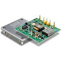
DC/DC Converters & Regulators 12 Vdc 8.3A Iso Input 48V 100W
Manufacturer
Ericsson Power Modules
Series
PKJ-Er
Datasheet
1.PKJ4618GEPI.pdf
(31 pages)
Specifications of PKJ4113EPI
Product
Isolated
Output Power
100 W
Input Voltage Range
36 V to 75 V
Number Of Outputs
1
Output Voltage (channel 1)
12 V
Output Current (channel 1)
8.3 A
Isolation Voltage
1.5 KV
Package / Case Size
Half Brick
Output Type
Isolated
Lead Free Status / Rohs Status
Lead free / RoHS Compliant
Available stocks
Company
Part Number
Manufacturer
Quantity
Price

Part Number:
PKJ4113EPI
Manufacturer:
ERICSSON/爱立信
Quantity:
20 000
Part Number:
PKJ4113EPIHS
Manufacturer:
ERICSSON/爱立信
Quantity:
20 000


E
EMC Specification
Conducted EMI measured according to EN55022, CISPR 22
and FCC part 15J (see test set-up). See Design Note 009 for
further information. The fundamental switching frequency is
140 kHz for PKJ 4810E PI @ V
Conducted EMI Input terminal value (typ)
EMI without filter
External filter (class B)
Required external input filter in order to meet class B in
EN 55022, CISPR 22 and FCC part 15J.
EMI with filter
Prepared (also subject responsible if other)
KI/EAB/FC/P Anders Wägmark
Approved
KM/EAB/FJB/GMF (Natalie Johansson)
PKJ 4000E series Direct Converters
Input 36-75 V, Output up to 30 A / 100 W
C1
C2
C5
C4
C3
C6
C7
I
= 53 V, max I
Filter components:
C1,2,6 = 0.68 µF
C3,7 = 47 µF
C4,5 = 3.9 nF
L1 = Common
mode inductor 768
µH
L2 = 15 µH
O
.
Checked
(MICMALE)
Ericsson Internal
PRODUCT SPECIFICATION
No.
3/1301-BMR623 Uen
Date
2008-11-21
Test set-up
Layout recommendations
The radiated EMI performance of the Product will depend on
the PCB layout and ground layer design. It is also important to
consider the stand-off of the product. If a ground layer is used,
it should be connected to the output of the product and the
equipment ground or chassis.
A ground layer will increase the stray capacitance in the PCB
and improve the high frequency EMC performance.
Output ripple and noise
Output ripple and noise measured according to figure below.
See Design Note 022 for detailed information.
Output ripple and noise test setup
Technical Specification
EN/LZT 146 383 R3A September 2009
© Ericsson AB
Rev
B
Reference
1 (6)
23
Related parts for PKJ4113EPI
Image
Part Number
Description
Manufacturer
Datasheet
Request
R

Part Number:
Description:
37.5-150W DC/DC POWER MODULES
Manufacturer:
Ericsson Power Modules
Part Number:
Description:
DC/DC Power Supply Dual-OUT 3.3V/5V 9.6A/6.4A 40W 10-Pin
Manufacturer:
Ericsson Power Modules
Part Number:
Description:
DC/DC Power Supply Single-OUT 3.3V 20A 66W 8-Pin Quarter-Brick
Manufacturer:
Ericsson Power Modules
Datasheet:
Part Number:
Description:
DC/DC Power Supply Single-OUT 1.8V 50A 90W 11-Pin
Manufacturer:
Ericsson Power Modules
Part Number:
Description:
Module DC-DC 1-OUT 1.8V 30A 54W 9-Pin
Manufacturer:
Ericsson Power Modules

Part Number:
Description:
Module DC-DC 1-OUT 1.8V 60A 108W 11-Pin Half-Brick
Manufacturer:
Ericsson Power Modules
Datasheet:

Part Number:
Description:
Module DC-DC 1-OUT 12V 25A 300W 11-Pin Half-Brick
Manufacturer:
Ericsson Power Modules
Part Number:
Description:
Module DC-DC 1-OUT 5V 20A 100W Quarter-Brick
Manufacturer:
Ericsson Power Modules

Part Number:
Description:
Module DC-DC 1-OUT 12V 6A 72W 8-Pin 1/8-Brick
Manufacturer:
Ericsson Power Modules
Datasheet:
Part Number:
Description:
Module DC-DC 1-OUT 5.05V 2A 10W 18-Pin SMD
Manufacturer:
Ericsson Power Modules
Part Number:
Description:
Manufacturer:
Ericsson Power Modules
Datasheet:

Part Number:
Description:
Module DC-DC 1-OUT 5V 60A 300W 11-Pin Half-Brick Tray
Manufacturer:
Ericsson Power Modules
Part Number:
Description:
Module DC-DC 1-OUT 12V 1A 12W 18-Pin
Manufacturer:
Ericsson Power Modules
Datasheet:
Part Number:
Description:
Module DC-DC 2-OUT 12V/-12V 0.25A 6W 18-Pin SMD
Manufacturer:
Ericsson Power Modules
Part Number:
Description:
Module DC-DC 1-OUT 28V 11A 310W 11-Pin Half-Brick Tray
Manufacturer:
Ericsson Power Modules
Datasheet: