PKJ4113EPI Ericsson Power Modules, PKJ4113EPI Datasheet - Page 24
PKJ4113EPI
Manufacturer Part Number
PKJ4113EPI
Description
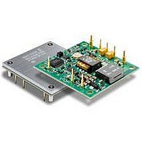
DC/DC Converters & Regulators 12 Vdc 8.3A Iso Input 48V 100W
Manufacturer
Ericsson Power Modules
Series
PKJ-Er
Datasheet
1.PKJ4618GEPI.pdf
(31 pages)
Specifications of PKJ4113EPI
Product
Isolated
Output Power
100 W
Input Voltage Range
36 V to 75 V
Number Of Outputs
1
Output Voltage (channel 1)
12 V
Output Current (channel 1)
8.3 A
Isolation Voltage
1.5 KV
Package / Case Size
Half Brick
Output Type
Isolated
Lead Free Status / Rohs Status
Lead free / RoHS Compliant
Available stocks
Company
Part Number
Manufacturer
Quantity
Price

Part Number:
PKJ4113EPI
Manufacturer:
ERICSSON/爱立信
Quantity:
20 000
Part Number:
PKJ4113EPIHS
Manufacturer:
ERICSSON/爱立信
Quantity:
20 000


E
Operating information
Input Voltage
The input voltage range 36 to 75 Vdc meets the requirements
of the European Telecom Standard ETS 300 132-2 for normal
input voltage range in –48 and –60 Vdc systems, -40.5 to -
57.0 V and –50.0 to -72 V respectively.
At input voltages exceeding 75 V, the power loss will be higher
than at normal input voltage and T
absolute max +125°C. The absolute maximum continuous
input voltage is 80 Vdc.
Turn-off Input Voltage
The products monitor the input voltage and will turn on and
turn off at predetermined levels.
The minimum hysteresis between turn on and turn off input
voltage is 1 V.
Remote Control (RC)
The maximum required sink current is 1 mA. When the RC pin
is left open, the voltage generated on the RC pin is
3.5 – 6.0 V. The standard product is provided with “negative
logic” remote control and will be off until the RC pin is
connected to the -In. To turn on the product the voltage
between RC pin and -In should be less than 1V. To turn off the
converter the RC pin should be left open, or connected to a
voltage higher than 4 V referenced to -In. In situations where it
is desired to have the product to power up automatically
without the need for control signals or a switch, the RC pin can
be wired directly to -In.
The second option is “positive logic” remote control, which can
be ordered by adding the suffix “P” to the end of the part
number. When the RC pin is left open, the product starts up
automatically when the input voltage is applied. Turn off is
achieved by connecting the RC pin to the -In. To ensure safe
turn off the voltage difference between RC pin and the -In pin
shall be less than 1V. The product will restart automatically
when this connection is opened.
See Design Note 021 for detailed information.
Input and Output Impedance
The impedance of both the input source and the load will
interact with the impedance of the product. It is important that
the input source has low characteristic impedance. The
products are designed for stable operation without external
capacitors connected to the input or output. The performance
Prepared (also subject responsible if other)
KI/EAB/FC/P Anders Wägmark
Approved
KM/EAB/FJB/GMF (Natalie Johansson)
PKJ 4000E series Direct Converters
Input 36-75 V, Output up to 30 A / 100 W
The products are fitted with a
remote control function referenced
to the primary negative input
connection (-In), with negative and
positive logic options available.
The RC function allows the product
to be turned on/off by an external
device like a semiconductor or
mechanical switch. The RC pin has
an internal pull up resistor to +In.
P1
must be limited to
Checked
(MICMALE)
Ericsson Internal
PRODUCT SPECIFICATION
No.
3/1301-BMR623 Uen
Date
2008-11-21
in some applications can be enhanced by addition of external
capacitance as described under External Decoupling
Capacitors.
If the input voltage source contains significant inductance, the
addition of a 22 - 100 µF capacitor across the input of the
product will ensure stable operation. The capacitor is not
required when powering the product from an input source with
an inductance below 10 µH. The minimum required
capacitance value depends on the output power and the input
voltage. The higher output power the higher input capacitance
is needed. Approximately doubled capacitance value is
required for a 24 V input voltage source compared to a 48V
input voltage source.
External Decoupling Capacitors
When powering loads with significant dynamic current
requirements, the voltage regulation at the point of load can
be improved by addition of decoupling capacitors at the load.
The most effective technique is to locate low ESR ceramic and
electrolytic capacitors as close to the load as possible, using
several parallel capacitors to lower the effective ESR. The
ceramic capacitors will handle high-frequency dynamic load
changes while the electrolytic capacitors are used to handle
low frequency dynamic load changes. It is equally important to
use low resistance and low inductance PCB layouts and
cabling.
External decoupling capacitors will become part of the control
loop of the DC/DC converter and may affect the stability
margins. As a “rule of thumb”, 100 µF/A of output current can
be added without any additional analysis. The ESR of the
capacitors is a very important parameter. Power Modules
guarantee stable operation with a verified ESR value of >10
mΩ across the output connections.
For further information please contact your local Ericsson
Power Modules representative.
Output Voltage Adjust (V
The products have an Output Voltage Adjust pin (V
pin can be used to adjust the output voltage above or below
Output voltage initial setting.
When increasing the output voltage, the voltage at the output
pins (including any remote sense compensation ) must be
kept below the threshold of the over voltage protection, (OVP)
to prevent the product from shutting down. At increased output
voltages the maximum power rating of the product remains the
same, and the max output current must be decreased
correspondingly.
To increase the voltage the resistor should be connected
between the V
Output voltage adjust function is according to information
given under the Output section for the respective product.
To decrease the output voltage, the resistor should be
connected between the V
adj
pin and +Sense pin. The resistor value of the
Technical Specification
EN/LZT 146 383 R3A September 2009
© Ericsson AB
Rev
B
adj
adj
pin and –Sense pin.
)
Reference
adj
). This
2 (6)
24
Related parts for PKJ4113EPI
Image
Part Number
Description
Manufacturer
Datasheet
Request
R

Part Number:
Description:
37.5-150W DC/DC POWER MODULES
Manufacturer:
Ericsson Power Modules
Part Number:
Description:
DC/DC Power Supply Dual-OUT 3.3V/5V 9.6A/6.4A 40W 10-Pin
Manufacturer:
Ericsson Power Modules
Part Number:
Description:
DC/DC Power Supply Single-OUT 3.3V 20A 66W 8-Pin Quarter-Brick
Manufacturer:
Ericsson Power Modules
Datasheet:
Part Number:
Description:
DC/DC Power Supply Single-OUT 1.8V 50A 90W 11-Pin
Manufacturer:
Ericsson Power Modules
Part Number:
Description:
Module DC-DC 1-OUT 1.8V 30A 54W 9-Pin
Manufacturer:
Ericsson Power Modules

Part Number:
Description:
Module DC-DC 1-OUT 1.8V 60A 108W 11-Pin Half-Brick
Manufacturer:
Ericsson Power Modules
Datasheet:

Part Number:
Description:
Module DC-DC 1-OUT 12V 25A 300W 11-Pin Half-Brick
Manufacturer:
Ericsson Power Modules
Part Number:
Description:
Module DC-DC 1-OUT 5V 20A 100W Quarter-Brick
Manufacturer:
Ericsson Power Modules

Part Number:
Description:
Module DC-DC 1-OUT 12V 6A 72W 8-Pin 1/8-Brick
Manufacturer:
Ericsson Power Modules
Datasheet:
Part Number:
Description:
Module DC-DC 1-OUT 5.05V 2A 10W 18-Pin SMD
Manufacturer:
Ericsson Power Modules
Part Number:
Description:
Manufacturer:
Ericsson Power Modules
Datasheet:

Part Number:
Description:
Module DC-DC 1-OUT 5V 60A 300W 11-Pin Half-Brick Tray
Manufacturer:
Ericsson Power Modules
Part Number:
Description:
Module DC-DC 1-OUT 12V 1A 12W 18-Pin
Manufacturer:
Ericsson Power Modules
Datasheet:
Part Number:
Description:
Module DC-DC 2-OUT 12V/-12V 0.25A 6W 18-Pin SMD
Manufacturer:
Ericsson Power Modules
Part Number:
Description:
Module DC-DC 1-OUT 28V 11A 310W 11-Pin Half-Brick Tray
Manufacturer:
Ericsson Power Modules
Datasheet: