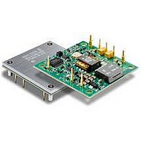
PKJ4113EPI Ericsson Power Modules, PKJ4113EPI Datasheet - Page 26

PKJ4113EPI
Manufacturer Part Number
PKJ4113EPI
Description
DC/DC Converters & Regulators 12 Vdc 8.3A Iso Input 48V 100W
Manufacturer
Ericsson Power Modules
Series
PKJ-Er
Datasheet
1.PKJ4618GEPI.pdf
(31 pages)
Specifications of PKJ4113EPI
Product
Isolated
Output Power
100 W
Input Voltage Range
36 V to 75 V
Number Of Outputs
1
Output Voltage (channel 1)
12 V
Output Current (channel 1)
8.3 A
Isolation Voltage
1.5 KV
Package / Case Size
Half Brick
Output Type
Isolated
Lead Free Status / Rohs Status
Lead free / RoHS Compliant
Available stocks
Company
Part Number
Manufacturer
Quantity
Price
Part Number:
PKJ4113EPI
Manufacturer:
ERICSSON/爱立信
Quantity:
20 000
Part Number:
PKJ4113EPIHS
Manufacturer:
ERICSSON/爱立信
Quantity:
20 000
Proper cooling of the product can be verified by measuring the
temperature at positions P1, P2 and P3. The temperature at
these positions should not exceed the max values provided in
the table below. The number of points may vary with different
thermal design and topology.
See Design Note 019 for further information.
Open frame
Base plate
Definition of reference temperature T
The reference temperature is used to monitor the temperature
limits of the product. Temperatures above maximum T
meassured at the reference point P1 are not allowed and may
cause degradation or permanent damage to the product. T
also used to define the temperature range for normal operating
conditions. T
safety margins, proper operation and high reliability ot the
product.
E
Position
P1
P2
P3
Prepared (also subject responsible if other)
KI/EAB/FC/P Anders Wägmark
Approved
KM/EAB/FJB/GMF (Natalie Johansson)
PKJ 4000E series Direct Converters
Input 36-75 V, Output up to 30 A / 100 W
P1
Description
Reference point, PCB
Core transformer
Reference point, Baseplate
is defined by the design and used to guarantee
P3
P1
Temp. limit
125º C
125º C
125º C
Checked
(MICMALE)
Airflow
Airflow
P1
,
P1
is
Ambient Temperature Calculation
For products with base plate the maximum allowed ambient
temperature can be calculated by using the thermal resistance.
1. The power loss is calculated by using the formula
((1/η) - 1) × output power = power losses (Pd).
η = efficiency of product. E.g. 89.5% = 0.895
2. Find the thermal resistance (Rth) in the Thermal Resistance
graph found in the Output section for each model. Note that
the thermal resistance can be significantly reduced if a
heat sink is mounted on the top of the base plate.
Calculate the temperature increase (∆T).
3. Max allowed ambient temperature is:
Max T
E.g. PKJ 4110E PIHS at 1 m/s:
1.
2. 13 W × 3.8°C/W = 50°C
3. 125 °C - 50°C = max ambient temperature is 75°C
The actual temperature will be dependent on several factors
such as the PCB size, number of layers and direction of
airflow.
Ericsson Internal
PRODUCT SPECIFICATION
No.
3/1301-BMR623 Uen
Date
2008-11-21
∆T = Rth x Pd
((
0.885
P1
1
- ∆T.
) -
1) × 100 W = 13 W
Technical Specification
EN/LZT 146 383 R3A September 2009
© Ericsson AB
Rev
B
Reference
4 (6)
26


