PKM4113DPINB Ericsson Power Modules, PKM4113DPINB Datasheet - Page 2
PKM4113DPINB
Manufacturer Part Number
PKM4113DPINB
Description
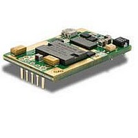
DC/DC Converters & Regulators 12 Vdc 11A Iso Input 36-75V 132W
Manufacturer
Ericsson Power Modules
Series
PKM-Dr
Datasheet
1.PKM4113DPINB.pdf
(29 pages)
Specifications of PKM4113DPINB
Product
Isolated
Output Power
30 W
Input Voltage Range
36 V to 75 V
Number Of Outputs
1
Output Voltage (channel 1)
1.5 V
Output Current (channel 1)
20 A
Isolation Voltage
1.5 KV
Package / Case Size
Quarter Brick
Output Type
Isolated
Lead Free Status / Rohs Status
Lead free / RoHS Compliant
Available stocks
Company
Part Number
Manufacturer
Quantity
Price

Part Number:
PKM4113DPINB
Manufacturer:
ERICSSON/爱立信
Quantity:
20 000


E
Prepared (also subject responsible if other)
EZHIXZH
Approved
PKM 4000D PINB series
DC/DC converters, Input 36-75 V, Output up to 35 A/132 W
Ordering Information
Product program
PKM 4110D PI
PKM 4111D PI
PKM 4113D PI
PKM 4115D PI
Product number and Packaging
Options
Remote Control logic
Baseplate
Hiccup OCP
Increased stand-off height
Lead length
Options
n
n
n
n
n
Example a through-hole mounted, positive logic, short pin
product with increased stand-off height would be
PKM 4111DPIPNBMLB.
* Standard variant (i.e. no option selected).
General Information
Reliability
The Mean Time Between Failure (MTBF) is calculated
at full output power and an operating ambient
temperature (T
in Information and Communication Technology (ICT)
equipment. Different methods could be used to
calculate the predicted MTBF and failure rate which
may give different results. Ericsson Power Modules
currently Telcordia SR332.
Predicted MTBF for the series is:
-
The Ericsson failure rate data system is based on field
tracking data. The data corresponds to actual failure
rates of components used in ICT equipment in
temperature controlled environments (T
1
2
3
4
5
1.67 million hours according to Telcordia SR332,
issue 1, Black box technique.
PKM 4XXXD PI n
A
) of +40°C, which is a typical condition
Description
P
NB
HC
M
LA
LB
Output
3.3 V, 35 A / 115 W
5 V, 25 A / 125 W
12 V, 11 A / 132 W
15 V, 8 A / 120 W
1
n
Negative *
Positive
Without baseplate *
With baseplate
Hiccup OCP
Standard stand-off height *
Increased stand-off height
5.30 mm *
3.69 mm
4.57 mm
n
ο
1
2
n
3
n
n
ο
4
2
n
A
5
= -5...+65°C).
n
ο
3
Checked
n
ο
4
n
ο
5
Ericsson Internal
PRODUCT SPECIFICATION
No.
1/1301-BMR 637 02 Uen
Date
2010-01-21
Compatibility with RoHS requirements
The products are compatible with the relevant clauses and
requirements of the RoHS directive 2002/95/EC and have a
maximum concentration value of 0.1% by weight in
homogeneous materials for lead, mercury, hexavalent
chromium, PBB and PBDE and of 0.01% by weight in
homogeneous materials for cadmium.
Exemptions in the RoHS directive utilized in Ericsson
Power Modules products include:
-
-
-
Quality Statement
The products are designed and manufactured in an
industrial environment where quality systems and methods
like ISO 9000, 6σ (sigma), and SPC are intensively in use
to boost the continuous improvements strategy. Infant
mortality or early failures in the products are screened out
and they are subjected to an ATE-based final test.
Conservative design rules, design reviews and product
qualifications, plus the high competence of an engaged
work force, contribute to the high quality of our products.
Warranty
Warranty period and conditions are defined in Ericsson
Power Modules General Terms and Conditions of Sale.
Limitation of Liability
Ericsson Power Modules does not make any other
warranties, expressed or implied including any warranty of
merchantability or fitness for a particular purpose
(including, but not limited to, use in life support
applications, where malfunctions of product can cause
injury to a person’s health or life).
© Ericsson AB 2009
The information and specifications in this technical
specification is believed to be correct at the time of
publication. However, no liability is accepted for
Telcordia SR332 is a commonly used standard method
intended for reliability calculations in ICT equipment.
The parts count procedure used in this method was
originally modelled on the methods from MIL-HDBK-
217F, Reliability Predictions of Electronic Equipment. It
assumes that no reliability data is available on the
actual units and devices for which the predictions are to
be made, i.e. all predictions are based on generic
reliability parameters.
Lead in high melting temperature type solder (used to
solder the die in semiconductor packages)
Lead in glass of electronics components and in
electronic ceramic parts (e.g. fill material in chip
resistors)
Lead as an alloying element in copper alloy containing
up to 4% lead by weight (used in connection pins
made of Brass)
Technical Specification
EN/LZT 146 416 R3A February 2010
© Ericsson AB
Rev
J
Reference
2 (4)
2
Related parts for PKM4113DPINB
Image
Part Number
Description
Manufacturer
Datasheet
Request
R

Part Number:
Description:
37.5-150W DC/DC POWER MODULES
Manufacturer:
Ericsson Power Modules
Part Number:
Description:
DC/DC Power Supply Dual-OUT 3.3V/5V 9.6A/6.4A 40W 10-Pin
Manufacturer:
Ericsson Power Modules
Part Number:
Description:
DC/DC Power Supply Single-OUT 3.3V 20A 66W 8-Pin Quarter-Brick
Manufacturer:
Ericsson Power Modules
Datasheet:
Part Number:
Description:
DC/DC Power Supply Single-OUT 1.8V 50A 90W 11-Pin
Manufacturer:
Ericsson Power Modules
Part Number:
Description:
Module DC-DC 1-OUT 1.8V 30A 54W 9-Pin
Manufacturer:
Ericsson Power Modules

Part Number:
Description:
Module DC-DC 1-OUT 1.8V 60A 108W 11-Pin Half-Brick
Manufacturer:
Ericsson Power Modules
Datasheet:

Part Number:
Description:
Module DC-DC 1-OUT 12V 25A 300W 11-Pin Half-Brick
Manufacturer:
Ericsson Power Modules
Part Number:
Description:
Module DC-DC 1-OUT 5V 20A 100W Quarter-Brick
Manufacturer:
Ericsson Power Modules

Part Number:
Description:
Module DC-DC 1-OUT 12V 6A 72W 8-Pin 1/8-Brick
Manufacturer:
Ericsson Power Modules
Datasheet:
Part Number:
Description:
Module DC-DC 1-OUT 5.05V 2A 10W 18-Pin SMD
Manufacturer:
Ericsson Power Modules
Part Number:
Description:
Manufacturer:
Ericsson Power Modules
Datasheet:

Part Number:
Description:
Module DC-DC 1-OUT 5V 60A 300W 11-Pin Half-Brick Tray
Manufacturer:
Ericsson Power Modules
Part Number:
Description:
Module DC-DC 1-OUT 12V 1A 12W 18-Pin
Manufacturer:
Ericsson Power Modules
Datasheet:
Part Number:
Description:
Module DC-DC 2-OUT 12V/-12V 0.25A 6W 18-Pin SMD
Manufacturer:
Ericsson Power Modules