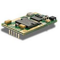
PKM4113DPINB Ericsson Power Modules, PKM4113DPINB Datasheet - Page 21

PKM4113DPINB
Manufacturer Part Number
PKM4113DPINB
Description
DC/DC Converters & Regulators 12 Vdc 11A Iso Input 36-75V 132W
Manufacturer
Ericsson Power Modules
Series
PKM-Dr
Datasheet
1.PKM4113DPINB.pdf
(29 pages)
Specifications of PKM4113DPINB
Product
Isolated
Output Power
30 W
Input Voltage Range
36 V to 75 V
Number Of Outputs
1
Output Voltage (channel 1)
1.5 V
Output Current (channel 1)
20 A
Isolation Voltage
1.5 KV
Package / Case Size
Quarter Brick
Output Type
Isolated
Lead Free Status / Rohs Status
Lead free / RoHS Compliant
Available stocks
Company
Part Number
Manufacturer
Quantity
Price
Part Number:
PKM4113DPINB
Manufacturer:
ERICSSON/爱立信
Quantity:
20 000
E
EMC Specification
Conducted EMI measured according to EN55022, CISPR 22
and FCC part 15J (see test set-up). See Design Note 009 for
further information. The fundamental switching frequency is
200 kHz for PKM 4111D PINB@ V
Conducted EMI Input terminal value (typ)
EMI without filter
External filter (class B)
Required external input filter in order to meet class B in
EN 55022, CISPR 22 and FCC part 15J.
EMI with filter
Prepared (also subject responsible if other)
EXUEFYA
Approved
SEC/D (Betty Wu)
PKM 4000D PINB series
DC/DC converters, Input 36-75 V, Output up to 35 A/132 W
C1
L1
C3
C4
C2
L2
C5
C6
DC/DC
I
= 53 V, max I
Load
Filter components:
C1,2,6 = 1 µF
Ceramic
C3,4 = 2.2 nF
Ceramic
C5 = 220 µF
Electrolytic
L1,2 = 0.81 mH
common mode
Checked
EQUENXU
O
.
Ericsson Internal
PRODUCT SPECIFICATION
No.
3/1301-BMR 637 02 Uen
Date
2009-11-20
Test set-up
Layout recommendations
The radiated EMI performance of the Product will depend on
the PCB layout and ground layer design. It is also important to
consider the stand-off of the product. If a ground layer is used,
it should be connected to the output of the product and the
equipment ground or chassis.
A ground layer will increase the stray capacitance in the PCB
and improve the high frequency EMC performance.
Output ripple and noise
Output ripple and noise measured according to figure below.
See Design Note 022 for detailed information.
Output ripple and noise test setup
Technical Specification
EN/LZT 146 416 R3A February 2010
© Ericsson AB
Rev
E
Reference
1 (6)
21


