USB2517I-JZX SMSC, USB2517I-JZX Datasheet - Page 53
USB2517I-JZX
Manufacturer Part Number
USB2517I-JZX
Description
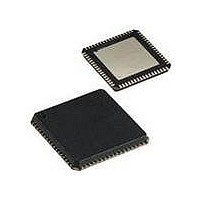
IC CTRLR USB2.0 7PORT 64QFN
Manufacturer
SMSC
Type
USB HUB Controllerr
Specifications of USB2517I-JZX
Controller Type
USB 2.0 Controller
Interface
Serial EEPROM
Voltage - Supply
3 V ~ 3.6 V
Current - Supply
130mA
Operating Temperature
-40°C ~ 85°C
Mounting Type
Surface Mount
Package / Case
64-QFN
Operating Supply Voltage
3.3 V
Maximum Operating Temperature
+ 85 C
Minimum Operating Temperature
- 40 C
Mounting Style
SMD/SMT
Operating Temperature Range
- 40 C to + 85 C
Supply Current
120 mA
Lead Free Status / Rohs Status
Lead free / RoHS Compliant
Other names
638-1090
Available stocks
Company
Part Number
Manufacturer
Quantity
Price

Part Number:
USB2517I-JZX
Manufacturer:
SMSC
Quantity:
20 000


USB 2.0 Hi-Speed Hub Controller
Datasheet
SMSC USB251x
8.3
8.3.1
8.3.2
8.3.2.1
Byte Count = N
S
1
8
D e n o te s M a s te r-to -S la v e
Slave Address
Instead of loading User-Defined Descriptor data from an external EEPROM, the SMSC hub can be
configured to receive a code load from an external processor via an SMBus interface. The SMBus
interface shares the same pins as the EEPROM interface; if CFG_SEL[1] & CFG_SEL[0] activate the
SMBus interface, external EEPROM support is no longer available (and the user-defined descriptor
data must be downloaded via the SMBus). The SMSC hub waits indefinitely for the SMBus code load
to complete and only “appears” as a newly connected device on USB after the code load is complete.
The hub’s SMBus implementation is a slave-only SMBus device. The implementation only supports
read block and write block protocols. The hub responds to other protocols as described in
8.3.3, "Invalid Protocol Response Behavior," on page
specification, Rev 1.0.
The SMBus interface is used to read and write the registers in the device. The register set is shown
in
SMBus Slave Addresses
The SMBus slave address is 58h (01011000b).
Bus Protocols
Typical Write Block and Read Block protocols are shown below. Register accesses are performed
using 7-bit slave addressing, an 8-bit register address field, and an 8-bit data field. The shading
indicates the hub driving data on the SMBDATA line; otherwise, host data is on the SDA/SMBDATA
line.
The slave address is the unique SMBus Interface Address for the hub that identifies it on SMBus. The
register address field is the internal address of the register to be accessed. The register data field is
the data that the host is attempting to write to the register or the contents of the register that the host
is attempting to read.
Note: Data bytes are transferred MSB first.
Block Read/Write
The block write begins with a slave address and a write condition. After the command code, the host
issues a byte count which describes how many more bytes will follow in the message. If a slave had
20 bytes to send, the first byte would be the number 20 (14h), followed by the 20 bytes of data. The
byte count may not be 0. A block read or write is allowed to transfer a maximum of 32 data bytes.
Note: For the following SMBus tables:
SMBus Slave Interface
Section 8.2.1, "Internal Register Set (Common to EEPROM and SMBus)," on page
7
A
1
Data byte 1
8
Wr
1
A
1
Figure 8.1 Block Write
A
1
Block Write
Register Address
DATASHEET
Data byte 2
53
8
D e n o te s S la v e -to -M a s te r
8
54. Reference the System Management Bus
1
A
A
1
...
Data byte N
8
Revision 1.1 (04-26-10)
35.
1
A
Section
P
1
Related parts for USB2517I-JZX
Image
Part Number
Description
Manufacturer
Datasheet
Request
R

Part Number:
Description:
IC USB 2.0 7PORT HUB CTLR 64QFN
Manufacturer:
SMSC
Datasheet:

Part Number:
Description:
FAST ETHERNET PHYSICAL LAYER DEVICE
Manufacturer:
SMSC Corporation
Datasheet:
Part Number:
Description:
357-036-542-201 CARDEDGE 36POS DL .156 BLK LOPRO
Manufacturer:
SMSC Corporation
Datasheet:
Part Number:
Description:
357-036-542-201 CARDEDGE 36POS DL .156 BLK LOPRO
Manufacturer:
SMSC Corporation
Datasheet:
Part Number:
Description:
357-036-542-201 CARDEDGE 36POS DL .156 BLK LOPRO
Manufacturer:
SMSC Corporation
Datasheet:
Part Number:
Description:
4-PORT USB2.0 HUB CONTROLLER
Manufacturer:
SMSC Corporation
Datasheet:
Part Number:
Description:
Manufacturer:
SMSC Corporation
Datasheet:
Part Number:
Description:
Manufacturer:
SMSC Corporation
Datasheet:
Part Number:
Description:
FDC37C672ENHANCED SUPER I/O CONTROLLER WITH FAST IR
Manufacturer:
SMSC Corporation
Datasheet:
Part Number:
Description:
COM90C66LJPARCNET Controller/Transceiver with AT Interface and On-Chip RAM
Manufacturer:
SMSC Corporation
Datasheet:
Part Number:
Description:
Manufacturer:
SMSC Corporation
Datasheet:
Part Number:
Description:
Manufacturer:
SMSC Corporation
Datasheet:
Part Number:
Description:
Manufacturer:
SMSC Corporation
Datasheet:
Part Number:
Description:
Manufacturer:
SMSC Corporation
Datasheet: