DS2482X-101+T Maxim Integrated Products, DS2482X-101+T Datasheet - Page 10
DS2482X-101+T
Manufacturer Part Number
DS2482X-101+T
Description
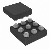
IC MASTER I2C-1WIRE 1CH 9-WLP
Manufacturer
Maxim Integrated Products
Datasheet
1.DS2482X-101T.pdf
(24 pages)
Specifications of DS2482X-101+T
Controller Type
I²C Bus Controller
Interface
I²C
Voltage - Supply
2.9 V ~ 5.5 V
Current - Supply
750µA
Operating Temperature
-40°C ~ 85°C
Mounting Type
Surface Mount
Package / Case
9-WLP
Lead Free Status / RoHS Status
Lead free / RoHS Compliant


Single-Channel 1-Wire Master with Sleep Mode
10
Command Code
Command Parameter
Description
Typical Use
Restriction
Error Response
Command Duration
1-Wire Activity
Read Pointer Position
Status Bits Affected
Configuration Bits Affected
Command Code
Command Parameter
Description
Typical Use
Restriction
Error Response
Command Duration
1-Wire Activity
Read Pointer Position
Status Bits Affected
Configuration Bits Affected
______________________________________________________________________________________
D2h
Configuration Byte
Writes a new configuration byte. The new settings take effect immediately. Note: When writing to
the Configuration Register, the new data is accepted only if the upper nibble (bits 7 to 4) is the
one’s complement of the lower nibble (bits 3 to 0). When read, the upper nibble is always 0h.
Defining the features for subsequent 1-Wire communication.
1-Wire activity must have ended before the DS2482-101 can process this command.
Command code and parameter are not acknowledged if 1WB = 1 at the time the command code
is received and the command is ignored.
None. The Configuration Register is updated on the rising SCL edge of the configuration-byte
acknowledge bit.
None
Configuration Register (to verify write).
RST set to 0.
1WS, SPU, APU updated.
B4h
None
Generates a 1-Wire reset/presence-detect cycle (Figure 4) at the 1-Wire line. The state of the
1-Wire line is sampled at t
Status Register, bits PPD and SD.
To initiate or end any 1-Wire communication sequence.
1-Wire activity must have ended before the DS2482-101 can process this command.
Command code is not acknowledged if 1WB = 1 at the time the command code is received and
the command is ignored.
t
acknowledge bit.
Begins maximum 262.5ns after the falling SCL edge of the command code acknowledge bit.
Status Register (for busy polling).
1WB (set to 1 for t
1WS and APU apply.
RSTL
+ t
RSTH
+ maximum 262.5ns, counted from the falling SCL edge of the command code
RSTL
+ t
RSTH
SI
and t
), PPD is updated at t
MSP
and the result is reported to the host processor through the
RSTL
+ t
MSP
, SD is updated at t
Write Configuration
1-Wire Reset
RSTL
+ t
SI
.
Related parts for DS2482X-101+T
Image
Part Number
Description
Manufacturer
Datasheet
Request
R

Part Number:
Description:
WLP/I°/SINGLE-CH 1-W LN DR LF UCSP PARTIAL
Manufacturer:
Maxim Integrated Products
Part Number:
Description:
WLP 8/I°/Single-Channel 1-Wire® Master with Sleep Mode
Manufacturer:
Maxim Integrated Products

Part Number:
Description:
IC MASTER I2C-1WIRE 1CH 9-WLP
Manufacturer:
Maxim Integrated Products
Datasheet:
Part Number:
Description:
MAX7528KCWPMaxim Integrated Products [CMOS Dual 8-Bit Buffered Multiplying DACs]
Manufacturer:
Maxim Integrated Products
Datasheet:
Part Number:
Description:
Single +5V, fully integrated, 1.25Gbps laser diode driver.
Manufacturer:
Maxim Integrated Products
Datasheet:
Part Number:
Description:
Single +5V, fully integrated, 155Mbps laser diode driver.
Manufacturer:
Maxim Integrated Products
Datasheet:
Part Number:
Description:
VRD11/VRD10, K8 Rev F 2/3/4-Phase PWM Controllers with Integrated Dual MOSFET Drivers
Manufacturer:
Maxim Integrated Products
Datasheet:
Part Number:
Description:
Highly Integrated Level 2 SMBus Battery Chargers
Manufacturer:
Maxim Integrated Products
Datasheet:
Part Number:
Description:
Current Monitor and Accumulator with Integrated Sense Resistor; ; Temperature Range: -40°C to +85°C
Manufacturer:
Maxim Integrated Products
Part Number:
Description:
TSSOP 14/A°/RS-485 Transceivers with Integrated 100O/120O Termination Resis
Manufacturer:
Maxim Integrated Products
Part Number:
Description:
TSSOP 14/A°/RS-485 Transceivers with Integrated 100O/120O Termination Resis
Manufacturer:
Maxim Integrated Products
Part Number:
Description:
QFN 16/A°/AC-DC and DC-DC Peak-Current-Mode Converters with Integrated Step
Manufacturer:
Maxim Integrated Products
Part Number:
Description:
TDFN/A/65V, 1A, 600KHZ, SYNCHRONOUS STEP-DOWN REGULATOR WITH INTEGRATED SWI
Manufacturer:
Maxim Integrated Products
Part Number:
Description:
Integrated Temperature Controller f
Manufacturer:
Maxim Integrated Products
Part Number:
Description:
SOT23-6/I°/45MHz to 650MHz, Integrated IF VCOs with Differential Output
Manufacturer:
Maxim Integrated Products