DS2482X-101+T Maxim Integrated Products, DS2482X-101+T Datasheet - Page 6
DS2482X-101+T
Manufacturer Part Number
DS2482X-101+T
Description
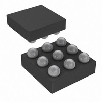
IC MASTER I2C-1WIRE 1CH 9-WLP
Manufacturer
Maxim Integrated Products
Datasheet
1.DS2482X-101T.pdf
(24 pages)
Specifications of DS2482X-101+T
Controller Type
I²C Bus Controller
Interface
I²C
Voltage - Supply
2.9 V ~ 5.5 V
Current - Supply
750µA
Operating Temperature
-40°C ~ 85°C
Mounting Type
Surface Mount
Package / Case
9-WLP
Lead Free Status / RoHS Status
Lead free / RoHS Compliant


Single-Channel 1-Wire Master with Sleep Mode
The DS2482-101 has three registers that the I
can read: Configuration, Status, and Read Data. These
registers are addressed by a read pointer. The position
of the read pointer, i.e., the register that the host reads
in a subsequent read access, is defined by the instruc-
tion the DS2482-101 executed last. To enable certain
1-Wire features, the host has read and write access to
the Configuration Register.
The DS2482-101 supports three 1-Wire features that
are enabled or selected through the Configuration
Register. These features are:
• Active Pullup (APU)
• Strong Pullup (SPU)
• 1-Wire Speed (1WS)
These features can be selected in any combination.
While APU and 1WS maintain their state, SPU returns to
its inactive state as soon as the strong pullup has
ended.
After a device reset (power-up cycle or initiated by the
Device Reset command), the Configuration Register
reads 00h. When writing to the Configuration Register,
the new data is accepted only if the upper nibble (bits 7
to 4) is the one’s complement of the lower nibble (bits 3
to 0). When read, the upper nibble is always 0h.
Figure 2. Rising Edge Pullup
6
_______________________________________________________________________________________
BIT 7
V
V
IL1(MAX)
IH1(MIN)
BIT 6
V
CC
0V
1-Wire BUS IS DISCHARGED
Configuration Register
Device Registers
BIT 5
1
APU = 1
t
1
2
BIT 4
C host
t
2
t
APUOT
The APU bit controls whether an active pullup (con-
trolled slew-rate transistor) or a passive pullup (R
resistor) is used to drive a 1-Wire line from low to high.
When APU = 0, active pullup is disabled (resistor
mode). Active pullup should always be selected unless
there is only a single slave on the 1-Wire line. The
active pullup does not apply to the rising edge of a
presence pulse or a recovery after a short on the
1-Wire line.
The circuit that controls rising edges (Figure 2) oper-
ates as follows: At t
or 1-Wire slave) ends. From this point on the 1-Wire bus
is pulled high through R
101. V
determine the slope. In case that active pullup is dis-
abled (APU = 0), the resistive pullup continues, as rep-
resented by the solid line. With active pullup enabled
(APU = 1), and when at t
level between V
actively pulls the 1-Wire line high, applying a controlled
slew rate as represented by the dashed line. The active
pullup continues until t
time on the resistive pullup continues. See the Strong
Pullup (SPU) section for a way to keep the pullup tran-
sistor conducting beyond t
BIT 3
1WS
Configuration Register Bit Assignment
CC
t
3
and the capacitive load of the 1-Wire line
IL1(MAX)
APU = 0
BIT 2
SPU
1
, the pulldown (from DS2482-101
APUOT
and V
WPU
2
3
.
the voltage has reached a
is expired at t
IH1(MIN)
internal to the DS2482-
BIT 1
0
Active Pullup (APU)
, the DS2482-101
3
. From that
BIT 0
APU
WPU
Related parts for DS2482X-101+T
Image
Part Number
Description
Manufacturer
Datasheet
Request
R

Part Number:
Description:
WLP/I°/SINGLE-CH 1-W LN DR LF UCSP PARTIAL
Manufacturer:
Maxim Integrated Products
Part Number:
Description:
WLP 8/I°/Single-Channel 1-Wire® Master with Sleep Mode
Manufacturer:
Maxim Integrated Products

Part Number:
Description:
IC MASTER I2C-1WIRE 1CH 9-WLP
Manufacturer:
Maxim Integrated Products
Datasheet:
Part Number:
Description:
MAX7528KCWPMaxim Integrated Products [CMOS Dual 8-Bit Buffered Multiplying DACs]
Manufacturer:
Maxim Integrated Products
Datasheet:
Part Number:
Description:
Single +5V, fully integrated, 1.25Gbps laser diode driver.
Manufacturer:
Maxim Integrated Products
Datasheet:
Part Number:
Description:
Single +5V, fully integrated, 155Mbps laser diode driver.
Manufacturer:
Maxim Integrated Products
Datasheet:
Part Number:
Description:
VRD11/VRD10, K8 Rev F 2/3/4-Phase PWM Controllers with Integrated Dual MOSFET Drivers
Manufacturer:
Maxim Integrated Products
Datasheet:
Part Number:
Description:
Highly Integrated Level 2 SMBus Battery Chargers
Manufacturer:
Maxim Integrated Products
Datasheet:
Part Number:
Description:
Current Monitor and Accumulator with Integrated Sense Resistor; ; Temperature Range: -40°C to +85°C
Manufacturer:
Maxim Integrated Products
Part Number:
Description:
TSSOP 14/A°/RS-485 Transceivers with Integrated 100O/120O Termination Resis
Manufacturer:
Maxim Integrated Products
Part Number:
Description:
TSSOP 14/A°/RS-485 Transceivers with Integrated 100O/120O Termination Resis
Manufacturer:
Maxim Integrated Products
Part Number:
Description:
QFN 16/A°/AC-DC and DC-DC Peak-Current-Mode Converters with Integrated Step
Manufacturer:
Maxim Integrated Products
Part Number:
Description:
TDFN/A/65V, 1A, 600KHZ, SYNCHRONOUS STEP-DOWN REGULATOR WITH INTEGRATED SWI
Manufacturer:
Maxim Integrated Products
Part Number:
Description:
Integrated Temperature Controller f
Manufacturer:
Maxim Integrated Products
Part Number:
Description:
SOT23-6/I°/45MHz to 650MHz, Integrated IF VCOs with Differential Output
Manufacturer:
Maxim Integrated Products