DS2482X-101+T Maxim Integrated Products, DS2482X-101+T Datasheet - Page 14
DS2482X-101+T
Manufacturer Part Number
DS2482X-101+T
Description
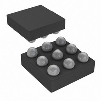
IC MASTER I2C-1WIRE 1CH 9-WLP
Manufacturer
Maxim Integrated Products
Datasheet
1.DS2482X-101T.pdf
(24 pages)
Specifications of DS2482X-101+T
Controller Type
I²C Bus Controller
Interface
I²C
Voltage - Supply
2.9 V ~ 5.5 V
Current - Supply
750µA
Operating Temperature
-40°C ~ 85°C
Mounting Type
Surface Mount
Package / Case
9-WLP
Lead Free Status / RoHS Status
Lead free / RoHS Compliant


Single-Channel 1-Wire Master with Sleep Mode
Table 3. Bit Allocation in the Direction Byte
x = Don’t care.
14
Command Code
Command Parameter
Description
Typical Use
Restriction
Error Response
Command Duration
1-Wire Activity
Read Pointer Position
Status Bits Affected
Configuration Bits Affected
BIT 7
______________________________________________________________________________________
V
BIT 6
x
78h
Direction Byte
Generates three time slots: two read time slots and one write time slot at the 1-Wire line. The type
of write time slot depends on the result of the read time slots and the direction byte. The direction
byte determines the type of write time slot if both read time slots are 0 (a typical case). In this
case, the DS2482-101 generates a write-one time slot if V = 1 and a write-zero time slot if V = 0.
See Table 3.
If the read time slots are 0 and 1, they are followed by a write-zero time slot.
If the read time slots are 1 and 0, they are followed by a write-one time slot.
If the read time slots are both 1 (error case), the subsequent write time slot is a write-one.
To perform a 1-Wire Search ROM sequence; a full sequence requires this command to be
executed 64 times to identify and address one device.
1-Wire activity must have ended before the DS2482-101 can process this command.
Command code and direction byte is not acknowledged if 1WB = 1 at the time the command
code is received and the command is ignored.
3 x t
direction byte.
Begins maximum 262.5ns after the falling SCL edge of the MSB of the direction byte.
Status Register (for busy polling).
1WB (set to 1 for 3 x t
second t
1WS, APU apply.
SLOT
BIT 5
MSR
x
+ maximum 262.5ns, counted from the falling SCL edge of the first bit (MSB) of the
(i.e., at t
SLOT
SLOT
BIT 4
x
), SBR is updated at the first t
+ t
MSR
).
BIT 3
x
MSR
BIT 2
x
, TSB and DIR are updated at the
BIT 1
x
1-Wire Triplet
BIT 0
x
Related parts for DS2482X-101+T
Image
Part Number
Description
Manufacturer
Datasheet
Request
R

Part Number:
Description:
WLP/I°/SINGLE-CH 1-W LN DR LF UCSP PARTIAL
Manufacturer:
Maxim Integrated Products
Part Number:
Description:
WLP 8/I°/Single-Channel 1-Wire® Master with Sleep Mode
Manufacturer:
Maxim Integrated Products

Part Number:
Description:
IC MASTER I2C-1WIRE 1CH 9-WLP
Manufacturer:
Maxim Integrated Products
Datasheet:
Part Number:
Description:
MAX7528KCWPMaxim Integrated Products [CMOS Dual 8-Bit Buffered Multiplying DACs]
Manufacturer:
Maxim Integrated Products
Datasheet:
Part Number:
Description:
Single +5V, fully integrated, 1.25Gbps laser diode driver.
Manufacturer:
Maxim Integrated Products
Datasheet:
Part Number:
Description:
Single +5V, fully integrated, 155Mbps laser diode driver.
Manufacturer:
Maxim Integrated Products
Datasheet:
Part Number:
Description:
VRD11/VRD10, K8 Rev F 2/3/4-Phase PWM Controllers with Integrated Dual MOSFET Drivers
Manufacturer:
Maxim Integrated Products
Datasheet:
Part Number:
Description:
Highly Integrated Level 2 SMBus Battery Chargers
Manufacturer:
Maxim Integrated Products
Datasheet:
Part Number:
Description:
Current Monitor and Accumulator with Integrated Sense Resistor; ; Temperature Range: -40°C to +85°C
Manufacturer:
Maxim Integrated Products
Part Number:
Description:
TSSOP 14/A°/RS-485 Transceivers with Integrated 100O/120O Termination Resis
Manufacturer:
Maxim Integrated Products
Part Number:
Description:
TSSOP 14/A°/RS-485 Transceivers with Integrated 100O/120O Termination Resis
Manufacturer:
Maxim Integrated Products
Part Number:
Description:
QFN 16/A°/AC-DC and DC-DC Peak-Current-Mode Converters with Integrated Step
Manufacturer:
Maxim Integrated Products
Part Number:
Description:
TDFN/A/65V, 1A, 600KHZ, SYNCHRONOUS STEP-DOWN REGULATOR WITH INTEGRATED SWI
Manufacturer:
Maxim Integrated Products
Part Number:
Description:
Integrated Temperature Controller f
Manufacturer:
Maxim Integrated Products
Part Number:
Description:
SOT23-6/I°/45MHz to 650MHz, Integrated IF VCOs with Differential Output
Manufacturer:
Maxim Integrated Products