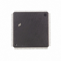
DP83905AVQB National Semiconductor, DP83905AVQB Datasheet - Page 14

DP83905AVQB
Manufacturer Part Number
DP83905AVQB
Description
IC CONTROLR AT/LAN TP IN 160PQFP
Manufacturer
National Semiconductor
Series
AT/LANTIC™r
Datasheet
1.DP83905AVQB.pdf
(80 pages)
Specifications of DP83905AVQB
Controller Type
AT, LAN Twisted-Pair Interface Controller
Voltage - Supply
4.75 V ~ 5.25 V
Current - Supply
100mA
Operating Temperature
0°C ~ 70°C
Mounting Type
Surface Mount
Package / Case
160-BFQFP
Lead Free Status / RoHS Status
Contains lead / RoHS non-compliant
Interface
-
Other names
*DP83905AVQB
Available stocks
Company
Part Number
Manufacturer
Quantity
Price
Company:
Part Number:
DP83905AVQB
Manufacturer:
Texas Instruments
Quantity:
10 000
Part Number:
DP83905AVQB
Manufacturer:
NS/国半
Quantity:
20 000
4 0 Functional Description
reads the next word in the EEPROM and appends this If in
8-bit mode it skips a word then reads and appends the next
word
Storing and Loading Configuration from EEPROM
If the EECONFIG pin is high during boot up the AT LANTIC
Controller’s configuration is read from the EEPROM before
the PROM data is read The configuration data is stored
within the upper two words of the EEPROM’s address
space Configuration Registers A and B are located in the
lower of these words Register C in the lower byte of the
upper word as shown in Figure 10
To write this configuration into the EEPROM the user must
follow the routine specified in the pseudo code below This
operation will work regardless of the level on EECONFIG
The EELOAD bit of Configuration Register B being set starts
the EEPROM write process Care should be taken not to
accidently set the GDLINK bit and therefore disable link in-
tegrity checking The next 3 writes to this register load the
values that will be stored in the configuration register (note
that the last 2 of these writes do not have to follow the
normal practice of preceding a write to this register with a
read to this address) The AT LANTIC Controller will then
commence the EEPROM write The write has been com-
pleted when the EELOAD bit goes to zero This loading pro-
cedure should be followed exactly and interrupts should be
disabled until it has completed to prevent any accidental
accesses to the AT LANTIC Controller
EEPROM LOAD()
4 4 JUMPERED AND JUMPERLESS OPERATION
SUPPORT
The AT LANTIC Controller supports several options that
enable the implementation of either a ‘‘jumpered’’ or ‘‘jump-
erless’’ power on configuration when installed into a stan-
dard PC compatible’s ISA bus A wide range of options are
provided to ensure that the AT LANTIC Controller can be
configured by an end user to function in all possible PC-AT
system configurations Several types of configuration op-
tions can be implemented examples including
1 Full jumper options All programmable options are select-
ed by utilizing jumpers on the board Option selection
requires no special software An example of this is
shown in the Figure 11
DISABLE INTERRUPTS()
value
value
value
WRITE(CONFIG B value)
READ(CONFIG B)
WRITE(CONFlG B config for A)
WRITE(CONFIG B config for B)
WRITE(CONFIG B config for C)
while (value AND EELOAD)
ENABLE INTERRUPTS()
e
e
e
value
WAIT()
READ(CONFIG B)
value AND 1 GDLINK
value OR EELOAD
e
READ(CONFIG B)
(Continued)
14
2 I O address jumpers only All other options configurable
3 Jumperless Special scheme provides contention-free
The AT LANTIC Controller’s Configuration Registers are
the key to providing the ability to implement various configu-
ration options These registers are configured by the same
method in shared memory and I O port modes 8- or 16-bit
modes The bit definitions of these registers are provided in
Section 5 All three registers are configured by hardware
selection during the Power-On-Reset of the system Two of
these registers can be configured via software (the Mode
Configuration Registers A and B) The third register (Hard-
ware Configuration Register C) is only configured during re-
set
The following table indicates most of the AT LANTIC Con-
troller options that a designer may like to have user configu-
rable (This list does not represent the complete list For the
full list see the Configuration register descriptions in
Section 5 )
The three basic options are described below Because of
the variety of programmable options there are a number of
variations possible only a few typical examples will be dis-
cussed
FULLY JUMPERED OPERATION
This option is shown in Figure 11 In this configuration most
options are selected by jumpers on the AT LANTIC Control-
ler’s memory bus For this option all configuration options
are set upon power-on by the AT LANTIC Controller as de-
scribed in Section 4 2 Accessing the configuration registers
is unnecessary and the EEPROM need only contain the
I O Base Address
Boot PROM Size
via software This option simplifies installation while max-
imizing compatibility
I O address selection
Media Selection
Interrupt No
Architecture
Boot PROM
Bus Timing
Address
Options
Option
TABLE I Some Configuration Options
for AT LANTIC Controller
Twisted Pair
4 Interrupts
IOCHRDY
I O Mode
Software
Disabled
0C000H
0C400H
0C800H
AUI Port
0300H
0240H
0280H
Mode
None
16k
Selections
MEM16 Mode
Thin Ethernet
Shared RAM
8 Interrupts
0CC00H
0DC00H
0D000H
0D400H
0D800H
02C0H
0320H
0340H
0360H
Mode
32k
64k


