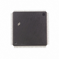
DP83905AVQB National Semiconductor, DP83905AVQB Datasheet - Page 25

DP83905AVQB
Manufacturer Part Number
DP83905AVQB
Description
IC CONTROLR AT/LAN TP IN 160PQFP
Manufacturer
National Semiconductor
Series
AT/LANTIC™r
Datasheet
1.DP83905AVQB.pdf
(80 pages)
Specifications of DP83905AVQB
Controller Type
AT, LAN Twisted-Pair Interface Controller
Voltage - Supply
4.75 V ~ 5.25 V
Current - Supply
100mA
Operating Temperature
0°C ~ 70°C
Mounting Type
Surface Mount
Package / Case
160-BFQFP
Lead Free Status / RoHS Status
Contains lead / RoHS non-compliant
Interface
-
Other names
*DP83905AVQB
Available stocks
Company
Part Number
Manufacturer
Quantity
Price
Company:
Part Number:
DP83905AVQB
Manufacturer:
Texas Instruments
Quantity:
10 000
Part Number:
DP83905AVQB
Manufacturer:
NS/国半
Quantity:
20 000
Bits
0–2
3–5
5 0 Register Descriptions
5 1 CONFIGURATION REGISTERS
These registers are used to configure the operation of the AT LANTIC Controller typically after power up These registers
control the configuration of bus interface setting options like interrupt selection I O base address and other specific modes
MODE CONFIGURATION REGISTER A
To prevent any accidental writes of this register it is ‘‘hidden’’ behind a previously unused register Register 0AH in the
AT LANTIC Controller’s Page 0 of registers was previously reserved on a read Now Configuration Register A can be read at
that address and can be written to by following a read to 0AH with a write to 0AH If any other AT LANTIC Controller register
accesses take place between the read and the write then the write to 0AH will access the Remote Byte Count Register 0
6
7
Symbols
IOAD0–
IOAD2
INT0–
INT2
FREAD
MEMIO
I O ADDRESS These three bits determine the base I O address of the AT LANTIC Controller within
the system’s I O map The AT LANTIC Controller occupies 20H bytes of the system’s address space
Note 1 When 001 is selected the AT LANTIC controller will not respond to any I O Addresses but will allow 4 consecutive writes to 278H to
write these three bits of this register This sequence will only operate once after a power-on reset This mode allows the AT LANTIC
Controller to be configured via software without conflicting with other peripherals
INTERRUPT LINE USED There are two interrupt modes which can be enabled by setting bit 5 of
Configuration Register C to the appropriate level
DIRECT DRIVE MODE In this mode an interrupt output pin will be driven active on a valid interrupt
condition Only one pin may be driven the other three will remain at TRI-STATE
determined by the value in this register
CODED OUTPUT MODE In this mode INT3 is the active interrupt output while pins INT0 to INT2 are
programmable outputs reflecting the values on bits 3 to 5
FAST READ When this bit is set high the AT LANTIC Controller in I O mode will begin the next port
fetch before the current IORD has completed In slow ISA systems this may cause the data in the port
to be overwritten before the ISA cycle has been completed
MEMORY OR I O MODE If this bit is set high then the AT LANTIC Controller is in shared memory
mode If it is set low it is in I O mode
Bit 5
0 0 0
0 0 1
0 1 0
0 1 1
1 0 0
1 0 1
1 1 0
1 1 1
X
X
X
X
MEMIO
7
0300H
Software (Note 1)
0240H
0280H
02C0H
0320H
0340H
0360H
FREAD
Bit 4
6
0
0
1
1
INT2
5
Bit 3
0
1
0
1
INT1
4
Interrupt
25
INT0
INT1
INT2
INT3
INT0
3
Function
IOAD2
2
IOAD1
1
IOAD0
0
The pin driven is


