PMR8210P Ericsson Power Modules, PMR8210P Datasheet - Page 14
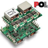
PMR8210P
Manufacturer Part Number
PMR8210P
Description
DC/DC Switching Controllers PoL Regul in 4.5-14V O/P 0.7-3.6 50A
Manufacturer
Ericsson Power Modules
Datasheet
1.PMR8210SR.pdf
(21 pages)
Specifications of PMR8210P
Number Of Outputs
1
Output Voltage
3 V to 5.25 V
Output Current
40 A
Output Power
132 W
Switching Frequency
600 KHz
Maximum Operating Temperature
+ 85 C
Minimum Operating Temperature
- 40 C
Lead Free Status / Rohs Status
Lead free / RoHS Compliant


Thermal Consideration
General
The regulators are designed to operate in different thermal
environments and sufficient cooling must be provided to
ensure reliable operation.
Cooling is achieved mainly by conduction, from the pins to the
host board, and convection, which is dependant on the airflow
across the regulator. Increased airflow enhances the cooling
of the regulator.
The typical Output Current Derating graph can be found in the
Output section for each model provides the available output
current vs. ambient air temperature and air velocity at V
V.
The product is tested on a 100 x 100 mm double-sided PCB
with 2 oz. copper and the direction of airfow fro pin 10 to pin
22. For surface mount packages, multiple vias must be
utilized.
Definition of product operating temperature
The product operating temperatures is used to monitor the
temperature of the product, and proper thermal conditions can
be verified by measuring the temperature at positions P1, P2,
and P3. The temperature at these positions (T
should not exceed the maximum temperatures in the table
below. The number of measurement points may vary with
different thermal design and topology. Temperatures above
maximum T
allowed and may cause permanent damage.
E
Position
P1
P2
P3
Prepared (also subject responsible if other)
ECOCOLO
Approved
SEC/D (Julia You)
PMR 8000 series PoL Regulator
Input 8 - 14 V, Output up to 40 A / 210 W
P1
Description
Reference point (Q501)
Inductor (L501)
Inductor (L502)
, measured at the reference point P1 are not
Max Temp.
T
T
T
P1
P2
P3
P1
=130º C
=130º C
=130º C
, T
Checked
EJANLLI
P2
, T
P3
I
= 12
,)
Ericsson Internal
PRODUCT SPECIFICATION
No.
3/1301-BMR 629 8210 Uen
Date
2009-09-28
Connections
Pin
1
2
3
Designation
CONFIG
Share
Comp
Technical Specification
EN/LZT 146 411 R1B November 2009
© Ericsson AB
Rev
C
Reference
Function
When two modules are
connected together to share
load current one must be
configured as the MASTER
and the other as the SLAVE.
This pin is used to configure
the module as either
MASTER or SLAVE. To
configure the module as the
MASTER, connect this pin to
GND. To condigure the
module as the SLAVE,
connect this pin to V
When not sharing current,
this pin should be connected
to GND.
This pin is used when
connecting two modules
together to share load
current. When two modules
are sharing the current the
Share pin of both modules
must be connected together.
When not sharing current,
this pin MUST be left open
(floating).
This pin is used when
connecting two modules
together to share load
current. When two modules
are sharing current the Comp
pin of bothe modules must be
connected together. When
not sharing current, this pin
MUST be left open (floating).
I
(pin 6).
6 (9)
14
Related parts for PMR8210P
Image
Part Number
Description
Manufacturer
Datasheet
Request
R

Part Number:
Description:
37.5-150W DC/DC POWER MODULES
Manufacturer:
Ericsson Power Modules
Part Number:
Description:
DC/DC Power Supply Dual-OUT 3.3V/5V 9.6A/6.4A 40W 10-Pin
Manufacturer:
Ericsson Power Modules
Part Number:
Description:
DC/DC Power Supply Single-OUT 3.3V 20A 66W 8-Pin Quarter-Brick
Manufacturer:
Ericsson Power Modules
Datasheet:
Part Number:
Description:
DC/DC Power Supply Single-OUT 1.8V 50A 90W 11-Pin
Manufacturer:
Ericsson Power Modules
Part Number:
Description:
Module DC-DC 1-OUT 1.8V 30A 54W 9-Pin
Manufacturer:
Ericsson Power Modules

Part Number:
Description:
Module DC-DC 1-OUT 1.8V 60A 108W 11-Pin Half-Brick
Manufacturer:
Ericsson Power Modules
Datasheet:

Part Number:
Description:
Module DC-DC 1-OUT 12V 25A 300W 11-Pin Half-Brick
Manufacturer:
Ericsson Power Modules
Part Number:
Description:
Module DC-DC 1-OUT 5V 20A 100W Quarter-Brick
Manufacturer:
Ericsson Power Modules

Part Number:
Description:
Module DC-DC 1-OUT 12V 6A 72W 8-Pin 1/8-Brick
Manufacturer:
Ericsson Power Modules
Datasheet:
Part Number:
Description:
Module DC-DC 1-OUT 5.05V 2A 10W 18-Pin SMD
Manufacturer:
Ericsson Power Modules
Part Number:
Description:
Manufacturer:
Ericsson Power Modules
Datasheet:

Part Number:
Description:
Module DC-DC 1-OUT 5V 60A 300W 11-Pin Half-Brick Tray
Manufacturer:
Ericsson Power Modules
Part Number:
Description:
Module DC-DC 1-OUT 12V 1A 12W 18-Pin
Manufacturer:
Ericsson Power Modules
Datasheet:
Part Number:
Description:
Module DC-DC 2-OUT 12V/-12V 0.25A 6W 18-Pin SMD
Manufacturer:
Ericsson Power Modules
Part Number:
Description:
Module DC-DC 1-OUT 28V 11A 310W 11-Pin Half-Brick Tray
Manufacturer:
Ericsson Power Modules
Datasheet: